Plastic components designing(plastic layout design ) is really a complicated job involving numerous aspects that deal with a number of specifications from the application.
What purpose will the component become utilized?
What way does it match to other components inside the assembly?
How much loads will it meet with in use?
Additionally to functional and structural concerns, processing problems play a considerable role with the style of an injection molded plastic component for plastic mold company.
How the molten plastic goes into, fulfills, and cools down inside the cavity largely drives what kind the functions in that component should take.
Adhering to some standard guidelines of injection molded components design and style will lead to a component that, additionally to getting less complicated to manufacture and assemble, will generally be a lot stronger in service.
Dividing a component into standard groups can help you to construct your design by a reasonable manner although minimizing molding issues.
As a component is created, constantly hold in thoughts how the component is molded and what you’ll be able to do to decrease concerning.The following list some concerns in the design.
-
Wall thickness
wall thickness of injection molded Plastic products is usually around 0.80-3.00 mm, too much wall thickness would invite shrinkage easily and produce voids, as to too thin wall, it is difficult to fulfill the cavity.
Large sized plastic products need a little thicker wall thickness, while small sized one need a little thin wall thickness.
Generally,injection molding product take 1.0-2.0 mm, and wall thickness need to be as uniform as possible.
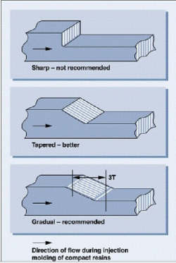
Worse comes to worst, some local places could be a little bit thicker or thinner, but it need to be gradually changed,with no shrinkage and fulfilling cavity oriented.
Generally it is hard to fulfill the cavity when the wall thickness of molded part is below 0.3 mm, but as to the soft plastic and rubber, the cavity could be filled under wall thickness 0.2~0.3 mm.


-
Ribs
Ribs are used as stiffening members along walls to avoid using thick sections to obtain the required stiffness.
Ribs can cause problems such as stress concentration and sinking. Sink marks are prominent behind ribs where the effective section is thick.
Ribs should therefore be thin, ideally between a third and a half of the wall thickness at the rib base. If a single thin rib does not give sufficient stiffening, a double rib can be used or,as an alternative,a thick rib can be used with a surface design feature to disguise the sink mark.
The rib height is generally recommended to be between three and five times the wall thickness unless the rib is supported laterally.
The number of ribs is also important and a number of small ribs are preferable to a single large rib to avoid distortion of the moulding on cooling.
Ribs along a wall need not be identical with regard to height and width. The corner where the rib joins the wall should be rounded with a minimum radius of 0.2 mm.
Most of the molded injection parts have enforcing ribs, for they could greatly increase its overall strength and stiffness without adding wall thickness .
The ribs are particularly useful for large size and heavy loading parts , while also they could prevent product deformation.
Thickness of ribs is usually 0.5-0.7 times of the overall thickness of plastic part. Rib thickness greater than 0.7 times of wall thickness is easy to lead to shrinkage.
Large and high ribs need 0.5-1 draft to help the ejection , while short ribs don’t need that.


-
Ejection Drafts(stripping draft) :
Components should be designed so that all surfaces perpendicular to the parting line are tapered so that the component can be ejected from the mould.
The draft angle depends upon the material and the shape and depth of the moulding.
The minimum draft angle is 0.5° with between 1.5° and 3° being normal. Thermoplastics shrink away from a wall cavity and onto the core on cooling.
To ensure that the moulding remains in the correct part of the mould prior to ejection, correct selection of draft angles for interior and exterior surfaces is essential.
For example, if the moulding is to remain on the core,the draft angle would be greater on the cavity side of the moulding. Draft angles for ribs and bosses should be at least 5°.
Plastic products are designed with stripping draft normally, but flatten shape(such as a plate), and some special requirements ( side walls is a large area but without draft,and it need add sliders ).
The ejection draft of the mold is usually 1-5 degrees ,often 2 degrees adopted, according to the specific demand of product size, height and shape.
The plastics design should be with smooth ejection and part full function oriented.
Usually the ejection draft of cavity should be 0.5 larger than that of the core side to help the part stay on the core side.
Normally shutoff position and kissoff position all need ejection draft.

-
Fillet (R):
Except the special requirements specify that the sharp edges are needed,the edges of molded part need to be filleted commonly to reduce the stress concentration and help the melt movement and easy ejection.
The minimum “R” is usually greater than 0.3 , for the too small “R” would lead to too much difficulties for plastic mold making.

-
Hole:
For the sake of the machining of plastic mold,it is better to make a simple ,round shape hole,and try not to make complex shaped hole as far as possible.
Diameter of hole shouldn’t be too small .The hole depth to hole diameter ratio shouldn’t be too big,for too long but thin mold core would be easily broken and deformed.
The proper distance between the hole and the outer edge of injection molding part is 1.5 times greater than the diameter of hole, and it is better that the distance between holes is 2 times greater than the hole diameter, so that the products own the necessary strength and stiffness.
The holes parallel to the direction of mold opening are formed by shut off or kiss off of the core and cavity insert.
If the holes aren’t parallel to the direction of mold opening,the lift or sliders are adopted to form those holes.
Without prejudice to the usage and assembly of parts,the holes on the side wall should be designed for shut off or kiss off forming possibly.

-
Boss
Bosses are used as supports for moulded inserts or as studs for use in assembling components.
Bosses should be designed to avoid sinking and sharp corners.
A boss wall thickness should be less than about three- quarters of the general wall thickness and sections other than circular should be avoided, partly to avoid stress and partly to reduce mould costs.
The position of the boss is important for the overall strength of the moulding and bosses are normally incorporated,via ribs if necessary, at corners or along wall sides.
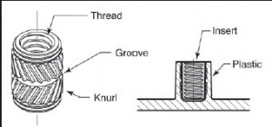
When the boss is to be used for metal inserts, it should be designed to receive the insert.
The metal insert itself should have no sharp corners and where knurled inserts are used, the knurling should be rounded.
In a properly designed system, the boss will shrink onto the insert on cooling because of the higher coefficient of expansion of plastics compared with metals.
When the boss is to be used for self-tapping screws,particular attention needs to be paid to the inside diameter and wall thickness.
A general recommendation is that the inside diameter should be the pitch of the screw and the outside diameter should be 2.5 times the screw diameter.
The boss should be free-standing to reduce stresses when the screw is driven home.
From a mould design point of view,mouldings incorporating bosses should have ejector pins or sleeves incorporated at the base of each boss in the cavity to facilitate extraction.
This also allows air to escape thus avoiding bum marks on the surface and incomplete filling of the cavity.
When the boss is to be used for metal inserts, it should be designed to receive the insert.
The metal insert itself should have no sharp corners and where knurled inserts are used, the knurling should be rounded.
In a properly designed system, the boss will shrink onto the insert on cooling bosses are typically used for peg-in-hole assembly of 2 plastic parts, or self-tapping assembly.
When boss is not very high and the ejection is finished by ejection sleeve, normally the draft isn’t necessary.
But When the boss is very high, usually we need four way reinforcement around the boss, with 1-2 degree draft, boss also need ejection draft sometimes.
When BOSS and pillars (or another boss) need match, the clearance fit usually takes unilateral assembly clearance 0.05-0.10 in order to fit the position error when processing.
When boss assembly is for self-tapping screws, its diameter should be 0.1~0.2 mm smaller than the diameter of screw to be able to screw tighten. Such as, if the self-tapping screw is M3.0, boss inner diameter usually is Ф2.60-2.80.

-
Insert
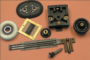
the already existing metal or plastic parts were positioned inside the mold for the second molding, those already existing components is called inserts.
When the plastic product design needs inserts, the inserts in the mold must be complete, accurate and reliable positioning, but also consider the insert must be firmly connected to the molded parts, when the plastic round the inserts is too little,the strength is poor there,also consider not leak melt plastic .
8. surface pattern:
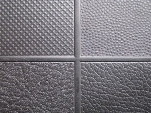
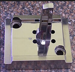
The surface of plastic products can be smooth surface (good Polish on cavity), EDM mark (mold cavity formed by electrode electrical discharge) ,texture and engraving surface.
The deep and big area texture need a bigger ejection draft angel.

-
Letter:
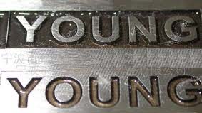
the text on the plastic surface may be concave or convex style .
The convex letter is formed by concave cavity ,while concave letter is formed by convex letter on the cavity,which is difficult to machine a bit.
-
Thread
Thread tolerance on plastic parts are usually not very high , and plastic mold sometimes need make a special unscrewing mechanism.
Under some condition for not so tight tolerance screw,the simple force ejection mechanism could be adopted.
-
Support surfaces:
plastic products usually do not need the entire surface as the support surface, but use ribs,convex stands as support .
It is difficult to achieve a large and absolute flat plane for injection molding , which is easily deformed and warp.


-
Corners
Corners should be rounded to avoid disruption of the melt flow as far as possible. Sharp corners disrupt the flow and this sets up internal stresses, especially with fiber reinforced materials.
Furthermore, the polymer shrinks onto the inside of the corner. Stress concentration at corners can lead to failure of the component in service and flow-induced stress encourages warping.
The inside corner radius should preferably be at least half the wall thickness although a quarter of the wall thickness is acceptable.
In any case, it should not be less than 0.5 mm.
The outside corner radius is the internal radius plus the wall thickness unless other factors determine otherwise.
-
Assembly of plastic products
the assembly of
1.ultrasonic welding, which is characterized by achieving on the mold, but the assembly process requires a special ultrasound machine, the cost increases, and the products can not be disassembled.
The cross-sectione of ultrasonic welding is a triangle wtih width 0.30 , height 0.30 and a length of 5-10mm, intermittent 2mm;
2. self-tapping assembly: it is characterized by achieving on the mold, but the assembly process increases the cost, and invite the disassembly trouble;
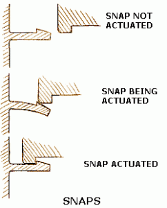
3 snap assembly :It is characterized by a more complex mold, easy to assemble and disassemble . snap assembly can be repeated many times.
There are various forms of snaps, but the key point is to avoid the some area big thickness ,and also consider the mold structure for the snap.
4. peg – in – hole assembly method, which is characterized by simple structure mold, easy to assemble and disassemble, but its drawback is not very strong.


-
Rabbet
two mating surfaces of plastic products usually adopt rabbet, the depth of rabbet is typically about 0.8-2.5, its side need a gap of about 0.1, too deep rabbet need 2 degree draft angel, while.
Mating surfaces of the upper and lower rabbet are usually contacted (that is, zero gap).
-
Surface treatment:
commonly used coating, screen printing, hot stamping, printing, plating, engraving, etch, polish and etc.
