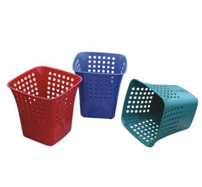
Industrail Plastic Dustbin Mould,waste bin mould and garbage bin mould making

120L Dustbin Mould/ Garbage bin Mould /Trash Bin Mould
- Cavity :1
- dustbin Size:932*492*550mm
- Mold Life:200,000 shots
- Injection Gate(Body):cold runner
- Injection Gate(Lid):1 drop hot runner,heat coil:”HOTSET” brand,Germany original.
- Mold Steel:P20
- Plastic Material:HDPE
Dustbin mold making and design
Design requirements of a molded plastic dustbin occasionally do not allow the dustbin to be removed directly from the plastic dustbin mold as it opens. This is true when the plastic dustbin is undercut with respect to the line of travel or of the opening and closing of the mold. The usual practice is to modify the design as much as possible in order to make the simplest mold.
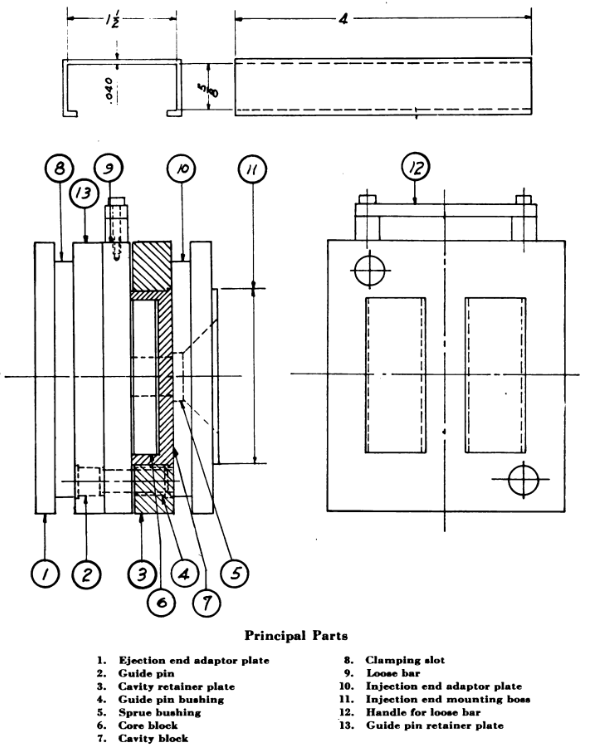
 The loose-bar type of injection dustbin mold is a useful design for overcoming the difficulty of ejecting a long draw, thin section dustbin. The sliding box cover shown in Fig.1. is a typical example of a dustbin which cannot readily be ejected directly on account of the long draw, 4 inches, and the thin section, .040 inch. Endwise molding which is required for direct ejection on opening the press is impractical with these characteristics. This is because the action of the ejector mechanism depends on the amount of opening travel. Also, the mold would be rather bulky—at least twice the length of the dustbin to allow space for the dustbin and for the ejector travel. By molding over a core attached to a loose bar, it will be possible to mold lettering on the top face of the box, as it will be drawn directly from the cavity as the mold opens. The loose-bar mold for the box cover is shown in Fig. 1. A side view and a view facing the ejection end platen are shown. The bar is to be removed manually and replaced by a duplicate bar so the dustbins may be stripped on a bench while the second bar is in the mold. No ejector device is required. The mold is simple, and consists of front and rear adaptor plates, cavity blocks and retainer, loose bar and core assembly, guide pins and retainer plate and the gating system.
Adaptor Plates
 The two adaptor plates serve as backing plates for guide pins, bushings and cavity blocks. The ejection end plate (detail 1) need not be hardened as the guide pins have practically no tendency to sink in. This plate is made of plain flat stock and cold rolled steel may be used. If it is desired to grind the plate flat, machine steel should be used, as it will not warp when the skin is removed. The injection end plate (detail 10) receives more severe service, as it is the backing plate for the cavity blocks. It should be hardened. This plate has a circular mounting boss and is bored out for entrance of the injection cylinder nose. No mounting boss is shown on the ejection end adaptor, as some designers prefer to let this end float and be located by the guide pins. A large hole in the press platen is not desirable as it weakens the platen enough to allow it to bend out of shape. On the injection end, it is necessary to have a rather large hole to allow the injection cylinder to enter as close as possible to the mold to prevent undue cooling of the plastics material as it travels through the nozzle into the sprue. So a mounting boss has been included on the injection end adaptor plate.

Fig 1.
Topworks,A dedicated garbage bin mould and waste bin mould maker