
A plastic mold is the single most expensive item in most injection molding projects, and its design decides far more than the tool price. It decides your part quality, your cycle time, your scrap rate, and how long the tool lasts before it needs repair. Yet many buyers treat mold design as the supplier’s internal business — something that happens after the purchase order.
It shouldn’t be. Buyers who understand the basics of plastic mold design write better RFQs (requests for quotation), spot weak supplier proposals, and avoid the design mistakes that inflate tooling cost. In short: plastic mold design is the engineering work of turning a 3D part model into a steel tool that fills, cools, and ejects reliably — millions of times over. This guide explains it from a mold maker’s point of view: what a good design looks like, which decisions drive cost and quality, and what information your supplier needs before quoting.
Last updated: October 2026
Key Takeaways
- What it is: Plastic mold design turns your part’s 3D model into a manufacturable steel tool — parting line, shrinkage compensation, gate and runner layout, cooling circuits, ejection, and steel selection.
- Why it matters: Most molding defects (sink marks, warpage, weld lines) are decided at the design stage. Fixing them after the steel is cut costs several times more than fixing them on paper.
- DFM basics: Uniform wall thickness (typically 1.0–3.0 mm), draft angles from 0.5° (polished) to 5° (heavy texture), and a radius on every internal corner.
- Steel choice: Match steel to volume and resin — P20 for general production, H13 for abrasive resins and very long runs, S136 stainless for corrosive resins like PVC.
- Before you quote: Send STEP files, the exact resin grade, annual volumes, and critical tolerances — and always ask for the supplier’s DFM report alongside the quote.
Why Mold Design Matters to Buyers
Sink marks, warpage, weld lines, inconsistent dimensions — most of these defects are locked in when the mold is designed, long before the first shot. Fixing a design flaw after the steel is cut typically costs several times more than fixing it on paper, because it means welding, re-machining, or in the worst case, cutting a new insert.
From a buyer’s perspective, mold design knowledge pays off in three concrete ways:
- Better quotes. When your RFQ includes the right technical details, suppliers quote against the same assumptions. You compare numbers instead of guessing what each quote left out.
- Fewer surprises. A buyer who knows what draft angles, gate positions, and cooling layouts should look like can review a supplier’s DFM (design for manufacturability) report critically instead of accepting it at face value.
- Lower total cost. In practice, part design decisions — wall thickness, tolerances, material choice — drive more of the final project cost than the hourly rate of the mold shop. A slightly simpler part in the right material often beats a cheaper mold quote.
How an Injection Mold Works
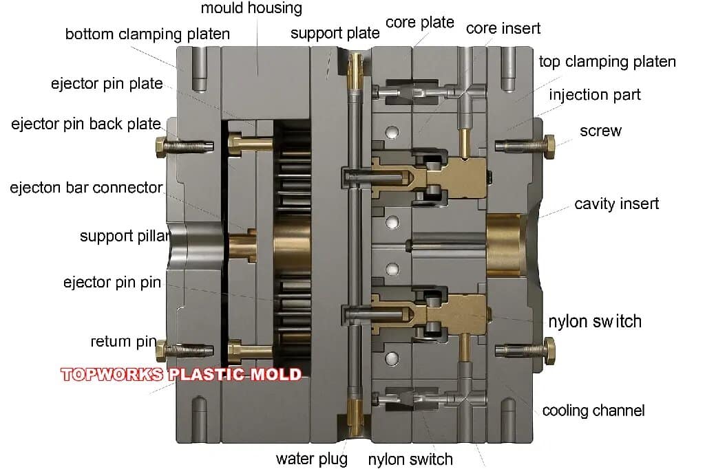
Before the design rules, a quick look at the tool itself. An injection mold has two main halves: the cavity side (A side) and the core side (B side). Molten plastic is injected through the sprue and runner system, fills the cavity, cools until solid, and is then pushed out by the ejection system. The mold opens and closes on the parting line — the plane where the two halves meet.
Three concepts shape almost every design decision that follows:
Shrinkage. Plastics shrink as they cool. Amorphous resins such as ABS or PC shrink relatively little (typically 0.4–0.7%), while semi-crystalline resins such as PP or nylon shrink more (1.0–2.5%). The mold cavity must be cut oversize by exactly the expected shrinkage rate. Get the rate wrong and every part comes out the wrong size — which is why the resin grade, including fillers like glass fiber, must be fixed before mold design starts.
Parting line. This is where the mold opens, and it leaves a witness line on the part. A good design places the parting line where the mark is least visible and where undercuts (features that would trap the part in the mold) are avoided or minimized. Every undercut that remains needs a slider or lifter — extra moving parts that add cost and maintenance.
Steel-safe design. When in doubt, experienced mold designers cut less steel, not more. It is far easier to remove steel later (to enlarge a feature) than to add it back by welding. This principle shows up everywhere: gate areas, thin walls, tight-tolerance features.
DFM: Designing Parts That Mold Well
DFM — design for manufacturability — is the review step where the mold maker checks your part design against what tooling can actually produce. Most reputable mold suppliers run a DFM analysis before quoting or cutting steel. Understanding the main DFM rules helps you design parts that are cheaper to tool and more consistent in production.
Wall Thickness: Keep It Uniform
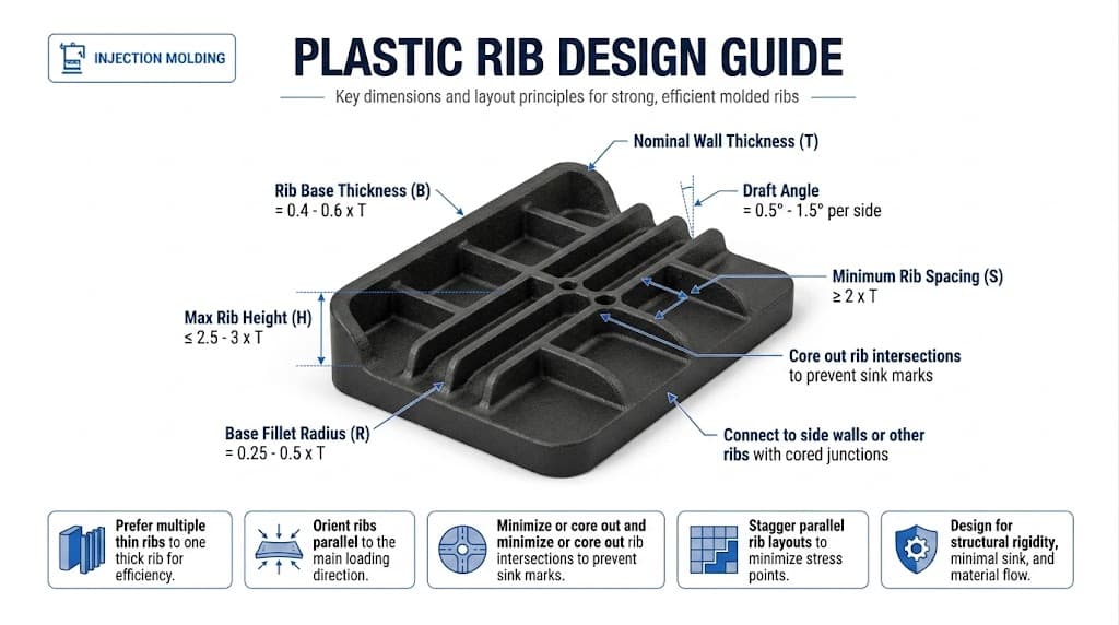
Uniform wall thickness is the first rule of moldable part design. Thick sections cool slower than thin ones, which causes sink marks on the surface and internal voids. As a rule of thumb, most commodity resins mold well at 1.0–3.0 mm wall thickness; thin-wall packaging can go below 1.0 mm with the right material and machine, while thick structural parts may need more.
The absolute value matters less than uniformity. If a part needs both thick and thin areas, use gradual transitions (a taper of at least 3:1 length-to-thickness change) rather than sudden steps. Where strength is needed, add ribs instead of thickening the whole wall — a rib 50–60% of the adjacent wall thickness adds stiffness with far less sink risk.
Draft Angles: Let the Part Release
Draft is a slight taper applied to vertical walls so the part releases from the mold instead of dragging. Without draft, parts stick, scuff, or need excessive ejection force. Typical minimums:
- Smooth, polished surfaces: 0.5°–1° per side
- Light texture: 1°–3° per side
- Heavy texture (leather grain): 3°–5° or more per side — deeper texture needs more draft, roughly 1° extra per 0.025 mm of texture depth
Draft should be added as early as possible in the CAD model. Adding it after tooling starts means re-cutting the cavity.
Radii and Fillets: Kill the Sharp Corners
Sharp internal corners are stress concentrators — parts crack there — and they are difficult to machine and polish in the mold. They also restrict plastic flow, which can cause incomplete filling. Put a radius on every internal corner — minimum 0.5 mm, ideally 25–50% of the adjacent wall thickness. External corners get a smaller radius, mainly to look finished and mold cleanly.
Ribs, Bosses, and Snap Fits
Ribs add stiffness without thick walls. Keep rib thickness at 50–60% of the wall, rib height under 3× wall thickness, and add 0.5°–1° draft per side.
Bosses (the round posts that receive screws or inserts) are sink-mark magnets because plastic piles up at their base. Design bosses as standalone features connected to walls with gussets, keep the outer diameter around 2.2–2.4× the insert or screw diameter, and core them out where possible.
Snap fits and living hinges need specific materials (PP and PE work; glass-filled nylons generally don’t for living hinges) and generous radii at the flex point. Flag these features in your RFQ — they affect both mold design and material choice.
Gate and Runner Design
The gate is the small opening where plastic enters the cavity, and the runner system is the channel network that delivers it there. Gate design affects filling pattern, weld line positions, cosmetic quality, and how much manual work each part needs after molding.
Common Gate Types
- Edge (side) gate. The workhorse: simple, easy to machine, good for medium to large parts. Leaves a visible gate mark on the part edge that usually needs trimming.
- Sub (tunnel) gate. Shears off automatically when the mold opens — no manual degating. Best for small parts in multi-cavity molds, but limited in the part thickness it can feed.
- Pinpoint gate. Used with three-plate molds; gates directly onto the part surface and separates automatically. Leaves a small witness mark on the cosmetic face.
- Hot-tip / valve gate. Part of a hot runner system (see below); plastic is injected directly with no cold runner waste. Valve gates add sequential control, useful for large or cosmetic parts.
Interactive Injection Molding Gate Types guide by
Gate position matters as much as gate type. Plastic should flow from thick sections toward thin ones, along the longest flow path, with the gate placed so weld lines fall in low-stress, non-cosmetic areas. Your supplier’s mold-flow simulation should confirm this before steel is cut — ask to see it.
Cold Runner vs. Hot Runner
A cold runner is a simple machined channel; the plastic in it solidifies with each shot and is ejected as scrap (or reground). It is cheaper to build and suits low volumes and frequent material or color changes.
A hot runner keeps the plastic molten inside heated manifold channels, so there is no runner scrap. It costs more upfront but pays back through material savings, shorter cycles, and automatic degating. Hot runners make sense for high volumes, expensive resins, and cosmetic parts — and they are close to mandatory for multi-cavity molds running engineering plastics.
Cooling System Design
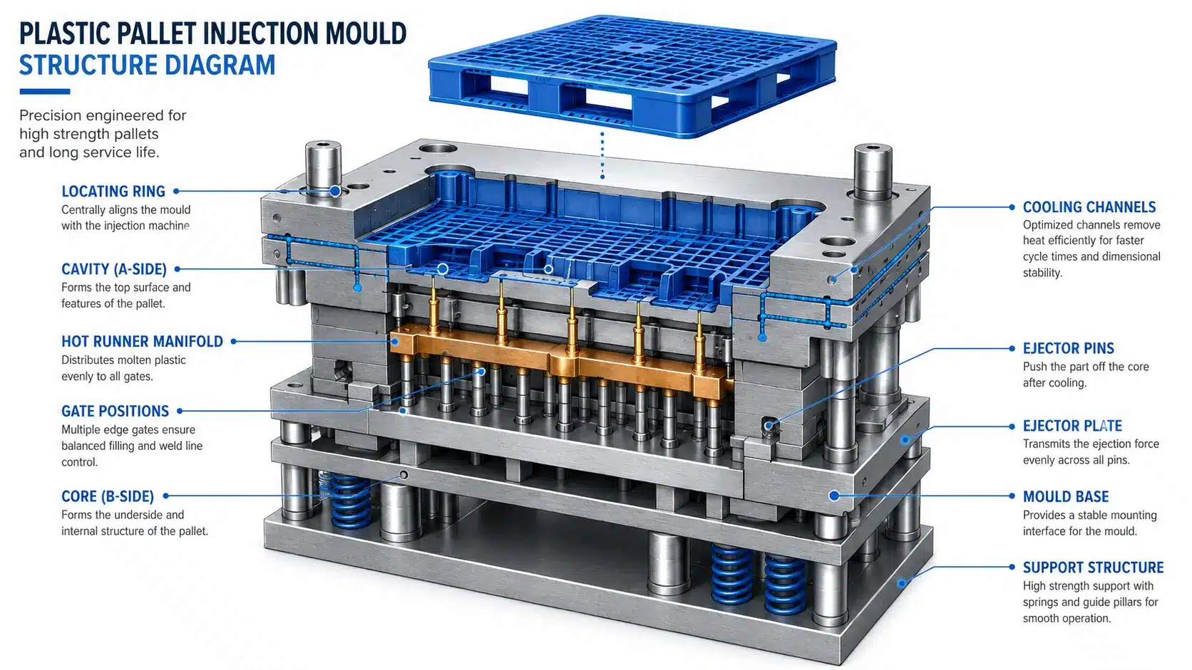
Cooling is the quiet cost driver of injection molding. In most shops it eats roughly half to two-thirds of total cycle time, so a good cooling layout produces more parts per hour from the same press — for the entire life of the mold.
A few principles matter:
- Uniformity over intensity. The goal is even temperature across the cavity, not maximum cold. Uneven cooling is a leading cause of warpage.
- Follow the part shape. Cooling channels should track the cavity contour at a consistent distance (typically 1.5–2× the channel diameter from the cavity wall). Straight drilled lines can’t do this on complex parts — that’s where baffles, bubblers, and, for difficult geometries, conformal cooling channels (3D-printed inserts with channels that follow the surface) earn their keep.
- Balance the circuits. In multi-cavity molds, each cavity should see the same coolant flow and temperature, or cavities will produce dimensionally different parts.
- Mind the material. Some resins need mold heat, not mold cooling — nylon and PC often run with mold temperatures above 80°C, which means the “cooling” system is really a temperature control system with heaters.
Ask your supplier how the cooling was designed, not just whether the mold has it. A mold-flow cooling analysis is standard practice on serious tooling.
Ejection System Design
Once the part is solid, it has to come out cleanly. The ejection system — usually a set of pins, and sometimes sleeves, stripper plates, or air assist — pushes the part off the core. Poor ejection design shows up as pin marks, distortion, or parts that stay stuck in the mold.
- Ejector pin placement should be on non-cosmetic surfaces, on ribs or bosses where the part is strongest. Pins on thin flat areas leave marks and can push through.
- Draft and polish do most of the release work; ejection force should be a backup, not the plan. Deep ribs or textured surfaces need extra draft.
- Undercuts need action. Any feature that prevents straight pull-off needs a slider (for external undercuts) or a lifter (for internal ones). Each one adds cost, cycle time, and a maintenance item — minimizing undercuts in part design is one of the highest-leverage DFM wins.
- Ejection must be balanced. Uneven ejection force warps parts. On large flat parts, a stripper plate often beats a handful of pins.
Choosing the Right Mold Steel
Mold steel is not a commodity choice — it sets the balance between tool cost, part quality, and tool life. The main families:
| Steel | Type | Typical use | Notes |
|---|---|---|---|
| P20 (1.2311) | Pre-hardened (~28–32 HRC) | General production molds, medium volumes | Machines easily, good polishability; the default choice for many tools |
| 718 (1.2738) | Improved P20 | Larger molds needing better uniformity | Better through-hardness than P20 on big blocks |
| H13 (1.2344) | Hot-work tool steel (~48–52 HRC) | High-wear, high-temperature, long-run tools | Handles glass-filled resins and high volumes; harder to machine |
| S136 / 420SS | Stainless (~48–52 HRC) | Corrosive resins (PVC), optical/medical parts | Corrosion resistance + mirror polish; premium price |
| NAK80 | Pre-hardened stainless-ish | Mirror-finish cosmetic parts | Excellent polishability without heat treatment distortion |
| 7075 aluminum | Aluminum | Prototypes, bridge tooling, very low volumes | Fast and cheap to cut; limited life |
Tool life expectations (typical figures — actual life depends on resin abrasiveness, maintenance, and molding conditions): P20-class tools commonly run several hundred thousand shots; hardened H13 or S136 tools are built for one million shots and beyond; aluminum tools are measured in thousands to tens of thousands. Match the steel to the job — paying for S136 on a 20,000-shot project wastes money, while P20 on a glass-filled, million-shot program guarantees premature wear.
Two special cases deserve mention. Corrosive resins such as PVC release corrosive gases and need stainless steel or protective plating. Abrasive resins — anything glass- or mineral-filled — wear gates and runners first; hardened inserts in those areas are cheap insurance.
Tolerances and Surface Finish
Tolerances: Specify Only What Matters
Tighter tolerances cost money twice: once in toolmaking (more precise machining, more sampling loops) and once in production (more process control, higher scrap). As a rough guide:
- General molded dimensions: ±0.1 mm is a comfortable, economical target for parts under ~100 mm.
- Precision features: ±0.05 mm is achievable but needs discussion — it constrains material choice (shrinkage variation) and usually requires steel-safe iterations.
- Below ±0.03 mm on molded plastic: possible only in special cases; expect significant cost and honest pushback from your supplier.
Put tolerances on a 2D drawing, not just in the 3D model. Mark which dimensions are critical (they drive the mold’s steel dimensions and the sampling plan) and which are reference. Standards like ISO 2768-m or DIN 16742 give a shared language — reference one in your drawing title block.
Surface Finish: The SPI Scale
Mold surface finish is specified on the SPI scale (Society of the Plastics Industry):
- SPI A-1 to A-3: mirror / high polish — cosmetic covers, lenses, premium consumer goods
- SPI B-1 to B-3: fine paper polish — general cosmetic parts
- SPI C-1 to C-3: stone / light texture — housings, industrial parts
- SPI D-1 to D-3: textured / matte — grips, heavy texture
Each step up in polish adds toolroom hours. Don’t specify mirror polish on a surface nobody sees. And remember the draft rule: heavier texture needs more draft angle, or parts will stick.
Common Design Defects and How to Prevent Them
| Defect | What you see | Usual design-side cause | Countermeasure |
|---|---|---|---|
| Sink marks | Dents on the surface opposite ribs/bosses | Thick sections cooling slower than walls | Core out bosses, thin the rib bases, keep walls uniform |
| Warpage | Part twists or bows after ejection | Uneven wall thickness, uneven cooling, poor gate balance | Uniform walls, balanced cooling, gate for symmetric fill |
| Flash | Thin plastic fins at the parting line | Worn parting line, excessive injection pressure, poor clamp | Proper shutoff design, adequate clamp tonnage, venting |
| Short shot | Incomplete fill, missing features | Thin walls, long flow paths, cold material | Increase wall thickness locally, move/add gates, check flow simulation |
| Weld (knit) lines | Visible lines where flow fronts meet | Holes, inserts, or multi-gate layouts splitting flow | Reposition gates so welds land in low-stress areas; raise melt/mold temperature |
| Splay / silver streaks | Streaky marks fanning from the gate | Moisture in resin, shear heating at the gate | Dry the resin, enlarge or reposition the gate |
| Jetting | Worm-like trails from the gate | Gate aimed into open cavity space | Aim the gate at a wall or obstruction to break the jet |
| Burn marks | Brown/black discoloration | Trapped air igniting (diesel effect) | Add or deepen vents at the last-fill areas |
Most of these are preventable at the design stage — which is exactly what a DFM review is for. If your supplier’s DFM report doesn’t mention venting, gate balance, or cooling, ask why.
From RFQ to T1: The Mold Design Workflow
Knowing the usual workflow helps you judge whether a supplier’s process is professional — and where you get to review and approve. The standard steps:
- RFQ and DFM review. You send the 3D model, resin, volumes, and tolerances. The mold maker returns a DFM report flagging design risks and required changes, plus the quote. Never skip the DFM — quoting without it means the supplier is guessing.
- Mold-flow simulation. Before steel is cut, the supplier simulates filling, cooling, and warpage. Ask to see the fill pattern and weld line predictions; this is where gate positions get validated.
- Mold design and your approval. The supplier produces the 3D mold design (not just the part model) — parting line, sliders, cooling, ejection, all of it. Serious shops send it for your sign-off. Review the parting line location and gate positions at this stage; changes afterward cost real money.
- Steel procurement and machining. Core and cavity blocks are ordered, then CNC-milled, EDM’d (electrical discharge machining, for sharp details and ribs), ground, and polished.
- Assembly and fitting. Plates, inserts, sliders, cooling fittings, and the hot runner (if any) are assembled and hand-fitted. This is skilled bench work — it’s where tolerances are truly made or lost.
- T1 tryout. The first shots. Expect adjustments: T1 samples are for checking dimensions and identifying fixes, not for approving production. Plan for at least one round of mold tuning before dimensions stabilize.
A supplier who can walk you through these steps with specifics — who shows you simulation results and asks for design approval — is demonstrating process maturity. One who jumps from quote to “mold finished” with no reviews in between is asking you to trust blindly.
What to Prepare Before You Send an RFQ
A complete RFQ package gets you faster, more comparable quotes. Before contacting mold makers, assemble:
- 3D CAD files — STEP format is the universal standard (IGES and native SolidWorks/CREO files also work). Make sure the model is the final revision, with draft and radii already applied if possible.
- 2D drawings — with critical dimensions, tolerances, datum structure, and surface finish callouts. The 3D model shows geometry; the drawing shows intent.
- Resin specification — exact grade and manufacturer if you have one (e.g., “SABIC PP 575P” beats “PP”), plus color, and any additives: glass fiber, flame retardant, UV stabilizer. Recycled content matters too — tell the supplier if the part must run recycled PP or similar.
- Volumes — expected annual usage and total project lifetime volume. This drives the cavity count and steel choice.
- Mold expectations — how many shots the tool should survive, who owns the mold, and where it will run (your molder’s press size constrains the mold size).
- Timeline — when you need T1 samples and when production must start. Be realistic: a complex multi-cavity tool is measured in weeks, not days.
- Quality documents — PPAP, dimensional reports, material certs — if your industry requires them (automotive and medical usually do).
Incomplete packages don’t just slow quoting — they produce quotes built on different assumptions, which makes them impossible to compare fairly.
FAQ
What is plastic mold design?
Plastic mold design is the engineering work of turning a part’s 3D model into a manufacturable steel tool: defining the parting line, shrinkage compensation, gate and runner layout, cooling circuits, ejection, and steel selection. Good mold design is what separates a tool that runs for a million shots from one that fights you from T1.
What is the difference between mold design and product design?
Product design defines what the part should do — its shape, function, and appearance. Mold design defines how to make it — how the steel tool opens, fills, cools, and ejects. DFM (design for manufacturability) is the bridge: the mold maker’s review of the product design against tooling reality.
How long does injection mold design take?
About a week for a simple single-cavity tool, three to four weeks for a complex multi-cavity mold with sliders and hot runners. That’s engineering time only — steel procurement, machining, and tryouts add more weeks on top.
Which mold steel should I choose?
Match steel to volume and resin. P20 is the economical default for general production; H13 suits abrasive resins and very long runs; S136 or equivalent stainless is for corrosive resins like PVC and for optical or medical parts needing mirror polish. Your mold maker should justify the choice against your annual volume — ask for the reasoning, not just the grade name.
What files does a mold maker need to quote?
At minimum: 3D CAD in STEP format, resin grade, color, expected annual volume, and any critical tolerances. A 2D drawing with tolerance and finish callouts makes the quote faster and more accurate. The more complete the package, the more comparable the quotes.
Can one mold produce parts in different colors?
Yes — color is a resin property, not a mold property. The same tool can run different colors with purging between runs. Purging takes machine time and material, so very frequent color changes are better planned as separate short runs.
What is a family mold?
A family mold produces several different parts in one cycle — useful when the parts are always used together in similar quantities and molded from the same material. It saves tooling cost but complicates balancing: parts with very different wall thicknesses or fill patterns can be hard to fill evenly in one tool.
How can I tell if a mold supplier’s DFM report is thorough?
A serious DFM covers draft angles, wall thickness uniformity, gate number and position with flow simulation, cooling layout, ejection concept, steel recommendation with reasoning, tolerance achievability, and a list of required part-design changes. If the “DFM” is two pages of generic text with no simulation images, treat it as a sales document, not engineering.
Getting It Right From the Start
Plastic mold design rewards buyers who engage early. Share your 3D files while the part design is still flexible, take the DFM review seriously, and judge suppliers on the quality of their engineering questions — a mold maker who challenges your draft angles and gate positions before quoting is usually the one whose tools run trouble-free for years.
If you’re preparing an RFQ, put together the package described above — STEP files, resin grade, volumes, tolerances — and ask each supplier for their DFM report alongside the quote. The report tells you more about the supplier than the price does.