Injection Mold Structure
The essence of plastic injection molding is an injection mold (which is used) to reproduce high-precision, multi-complex plastic components on a mass basis. High pressure is used to inject the molten plastic in a mold cavity where it is left to cool, solidify, and ejected. A typical injection mold is made out of two major halves: the fixed part (fixed half also known as the stationary half) and the moving part (moving half also known as the moving half) that come together to form the entire cavity.
I. Main Structural Components (by Function)
| Module | Key Components | Function Description |
|---|---|---|
| 1. Forming System | Cavity, Core, Inserts | Directly shapes the part’s external/internal surfaces and dimensions. |
| 2. Runner System | Sprue, Runners, Gate, Cold Slug Well | Guides molten plastic from nozzle → cavity. Gate type affects flow and appearance. |
| 3. Guiding System | Guide Pins, Guide Bushings | Ensures precise alignment during mold closing (accuracy ≤ 0.02 mm). |
| 4. Ejection System | Ejector Pins, Ejector Plate, Lifters, Slides | Forces the cooled part out of the mold. Slides for side actions (undercuts). |
| 5. Cooling System | Cooling Channels (straight, baffled, fountain) | Controls mold temperature (40–120°C) for rapid, uniform cooling. |
| 6. Venting System | Vent Slots, Parting Line Clearance, Vent Plugs | Expels trapped air/gas to prevent burn marks, voids, or short shots. |
| 7. Support System | Support Pillars, Spacer Blocks | Withstands injection pressure (100–200 MPa) to prevent plate deflection. |
| 8. Mold Base | Fixed Clamping Plate, Moving Clamping Plate, A/B Plates | Standard mold base (e.g., LKM, DME, FUTABA) provides mounting foundation. |
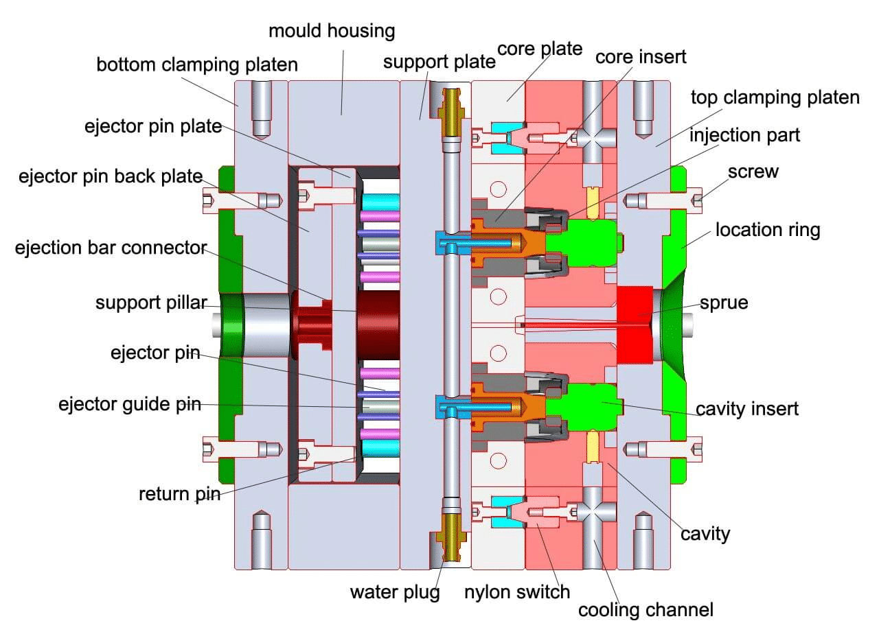
II. Typical Mold Cross-Section (Text Diagram)
[Injection Nozzle]
     ↓
[Sprue Bushing] → [Locating Ring]
     ↓
[Fixed Plate (A Plate)]
   ┌────────────────┐
   │  Cavity Insert │ ← Forms outer surface
   │  Cooling Lines │
   └────────────────┘
[Parting Line (PL)]
   ┌────────────────┐
   │   Core Insert  │ ← Forms inner surface
   │ Ejector Pins   │
   └────────────────┘
[Movable Plate (B Plate)]
     ↓
[Support Pillars, Ejector Plate]
     ↓
[Movable Clamping Plate]
     ↓
[Ejector Mechanism] → Connected to machine ejector rods
III. Key Component Details1. Runner System Design
| Component | Design Tips |
|---|---|
| Sprue | Taper 1:50–1:100, Ra 0.4 surface finish |
| Runners | Round/trapezoidal, short length, smooth corners |
| Gate Types | Pin gate (auto-cut), Submarine gate (scarless), Fan gate (large parts) |
2. Ejection Mechanisms
| Type | Application |
|---|---|
| Pin Ejection | Flat/simple parts |
| Angle Pin + Slide | Side holes, undercuts |
| Air/Hydraulic Core Pull | Deep ribs, thin walls |
| Double Ejection | Complex release sequence |
3. Cooling Optimization
- Channel diameter: Ø6–Ø12 mm
- Distance from cavity: 10–15 mm
- Use baffles or fountain wells for even cooling
- Temperature variation: ±2°C
IV. Molding Cycle (Standard Two-Plate Mold)
- Mold Close: Moving platen advances → guide pins align → parting line seals
- Injection: Melt fills cavity (0.1–3 sec)
- Packing: Compensates shrinkage (2–10 sec)
- Cooling: Part solidifies (10–60 sec)
- Mold Open: Moving platen retracts; part stays on moving side
- Ejection: Pins push part out → return pins reset
- Part Removal: Robot or manual → apply release agent → next cycle
V. Mold Classifications
| Type | Features |
|---|---|
| Two-Plate Mold | Simple, single parting line |
| Three-Plate Mold | Dual parting lines, auto gate cut |
| Hot Runner Mold | No runner waste, faster cycles |
| Stack Mold | Dual cavities, doubles output |
| IML/IMD Mold | In-mold labeling/decorating |
VI. Recommended Mold Steels
| Area | Steel Grade | Hardness (HRC) | Lifespan (shots) |
|---|---|---|---|
| Cavity/Core | P20, 718H | 30–36 | 300K–500K |
| Mirror/High Precision | NAK80, S136 | 38–42 | 500K–1M |
| High Wear | H13, SKD61 | 48–52 | 1M+ |
| Mold Base | S50C, 1045 | Pre-hardened | — |
VII. Design Guidelines
- Draft Angle: 1°–2° (external), 0.5°–1° (internal)
- Uniform Wall Thickness: 1.5–3.0 mm to avoid sink marks
- Fillet Radius: R ≥ 0.5 mm to reduce stress
- Venting: Parting line gap 0.02–0.04 mm or vent grooves
- Ejector Placement: On ribs or non-cosmetic areas
Summary:
Injection mold design is a precision engineering process integrating part design → mold structure → process parameters → material selection. Optimized design achieves:
- High efficiency (cycle < 30s)
- High quality (tolerance ±0.05 mm)

