
Injection Molding Engineering Guide
Gate Location in Injection Molding: How It Affects Appearance, Strength, and Cost
Pick the wrong gate spot and you’ll pay for it twice — once in scrap, once in tool rework. This guide is for buyers and sourcing teams quoting injection molded parts. Read it before you sign off on the DFM, not after T1 samples land on your desk.
What Is a Gate in Injection Molding?
A gate is the small opening between the runner and the cavity. Melt leaves the nozzle, travels down the runner, then enters the part through this gate. That entry point is your gate location.
The gate is kept small on purpose. A small gate freezes off fast after packing. That seals the cavity and lets the part eject clean. But the same small hole leaves a witness mark — and dictates which way the plastic travels.
Think of the gate as the source of a river. Where you place it decides how the water spreads and where currents collide. In molding the currents are flow fronts. Two fronts meet, you get a weld line.
Why Does Gate Location Matter for Buyers?
Gate location sets the ceiling on both quality and price. Bad gate, bad part. No amount of process tuning fully cleans up a defect the gate created. Once steel is cut, moving a gate means welding, re-machining, or a new insert.
For a buyer, the bill shows up everywhere. Higher reject rates. Inflated piece prices. Blemishes on the cosmetic face. Parts that snap at a weld line under load. Warped parts your assembly line cannot fit together. Delays while the molder reworks the tool.
Gate location gets decided during DFM, before any steel moves. That is the cheapest moment to push back. A ten-minute conversation at quoting saves weeks of rework. We see this play out on almost every program where the buyer stayed silent at DFM.
Gate Location in Injection Molding: How It Affects Appearance and Strength at a Glance
Gate location drives both appearance and strength through one shared mechanism. It controls the path the plastic takes to fill the cavity. That single flow pattern shapes nearly every cosmetic and structural outcome.
On the cosmetic side, the gate fixes where the witness mark sits, whether the surface shows jetting or blush, and where weld lines form. On the structural side, the same flow pattern locks in molecular and fiber orientation, places weld lines on or off the load path, and spreads residual stress around the part.
| Outcome | What Gate Location Controls | Buyer Impact |
|---|---|---|
| Appearance | Gate vestige position, weld line location, jetting, surface gloss | Cosmetic rejects, Class A surface failures |
| Strength | Weld line placement, fiber orientation, packing of thick sections | Field failures, low load capacity |
| Dimensional Stability | Differential shrinkage and warpage | Assembly fit, flatness, deflection |
| Cost & Yield | Fill balance, scrap rate, cycle time | Piece price, lead time |
Here is the trap. Appearance and strength are not two separate problems. They are two readings of the same flow pattern. A gate that solves the cosmetic side can wreck the structural side. Placement is always a trade-off.
How Does Gate Location Affect Part Appearance?
Gate location decides where surface defects appear and how visible they are. The gate always leaves evidence. Good placement just hides it.
Gate vestige (gate mark): Every gate leaves a small scar or nub where it detaches. Land it on a Class A surface and it shows. Put it on a hidden face, an interior rib, or a non-cosmetic edge.
Jetting: Plastic shoots into the open cavity as a thin stream before it spreads. The result is a worm-like surface mark. This often happens when a small gate fires into a large open space. Gate against a wall or into a feature instead, and the flow spreads smoothly.
Gate blush: A hazy halo forms around the gate when the material sees too much shear on entry. Usually it’s a gate too small, injection speed too high, or a land too long. Shear-sensitive resins suffer the most.
Weld lines (knit lines): Two flow fronts meet, a faint line forms. Gate location decides where they collide. One gate on a simple part means fewer weld lines. Add gates, holes, or cores — you add seams.
Flow and gloss differences: Long flow paths can leave flow marks or uneven gloss far from the gate. The far end looks duller than the near end.
Sink marks: Gate too far from a thick section, and you starve it during packing. A sink mark forms on the surface above it.
For cosmetic parts the rule is simple. Gate where the mark and the weld lines won’t be seen. Never fire an open jet across a visible surface.
How Does Gate Location Affect Part Strength?
Gate location controls where weld lines form, how chains and fibers line up, and where stress builds up. In most molded parts the weld line is the weakest point. The gate decides where that line lands.
Three Structural Mechanisms
1. Weld line strength. Two flow fronts meet, but the polymer doesn’t fully re-bond across the interface. The weld carries far less load than solid material. Simulation studies report 20% to 80% of the base (un-welded) material strength for unfilled resins. Worst case: a weld line holds one-fifth of the surrounding material’s load capacity. Don’t put weld lines in highly stressed areas.
2. Molecular and fiber orientation. Plastic chains and reinforcing fibers line up with the flow. A part is stronger along the flow and weaker across it. The gate sets flow direction — and therefore the direction of maximum strength. Align the flow with the main load path and the part holds up. Cross it, and the part splits along the grain.
3. Residual stress and packing. The area near the gate stays pressurized and packed the longest. Areas far from the gate run under-packed — weaker, prone to voids. Gate at or near the thickest load-bearing section for best packing where it counts. But watch the trade-off. Over-packing near the gate builds high residual stress and a zone prone to stress cracking. The standard fix is a declining-ramp hold pressure profile.
Put it bluntly: gate location places the weld lines, and weld lines decide where the part is most likely to break.
How Does Gate Location Cause Warpage and Deflection?
Gate location causes warpage by creating uneven shrinkage across the part. Plastic shrinks as it cools. When one region shrinks more than another, the part bends, twists, or bows.
Differential packing: Material near the gate packs out fully and shrinks less. Material far from the gate packs less and shrinks more. That mismatch pulls the part out of shape.
Flow-length imbalance: Gate at one end of a long part and the far end fills and cools differently from the near end. The bias bows the part.
Fiber orientation in filled resins: Glass fibers line up in the flow direction, blocking shrinkage along the flow axis but not across it. That gap between flow and cross-flow shrinkage — anisotropic shrinkage — is the leading deflection cause in reinforced parts. Gate location sets the fiber direction. So it directly controls the effect.
Cooling asymmetry: Gate location interacts with cooling layout. Uneven cooling plus uneven packing multiplies warpage. They compound. Fix one, the other still bites.
To cut deflection, molders aim for balanced fill. Center gating on symmetric parts. Balanced multi-gate layouts. Or a single gate that produces uniform flow length. For flat parts, thin-wall parts, or fiber-filled parts, deflection is usually the controlling design risk. Gate position is the first lever a molder reaches for.
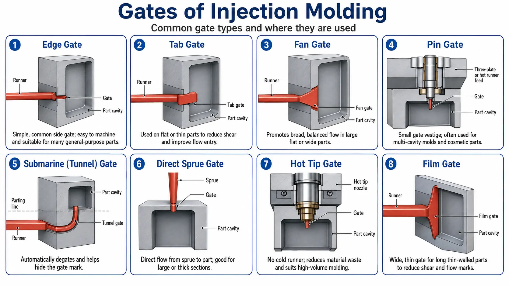
What Are the Common Gate Types and Where Do They Go?
Gate type and gate location get chosen together. The type defines how the gate connects and how it comes off. The location is where on the part it sits. These are the options you’ll see in any DFM report.
| Gate Type | Where It Is Used | Gate Mark | Notes |
|---|---|---|---|
| Edge (side) gate | On a parting-line edge of the part | Small tab, trimmed manually | Simple and economical; mark sits on the edge. The most common cold-runner gate type. |
| Tab gate | Edge of part, through a sacrificial tab | Trimmed off with the tab | Cuts stress and jetting near the gate. Tab is removed as a secondary step. |
| Fan gate | Wide, flat parts; cosmetic panels | Spread along an edge | Lets the melt spread evenly before entering the cavity. Reduces jetting and warpage. |
| Film gate | Large flat parts where warpage must stay low | Along one edge, trimmed | Produces parallel flow paths across the cavity. Typical gate height 0.5–2 mm. |
| Submarine (tunnel) gate | Below the parting line; where automatic degating is needed | Tiny mark, auto-trimmed on ejection | Separates itself when the mold opens. Gate angle typically 30–60°, usually 35–45°. Needs a non-brittle resin. The cashew/banana variant puts the gate on the back face for best cosmetics. |
| Pin / pinpoint gate | 3-plate mold or hot runner; top or any face of part | Very small dot | Flexible location; near-invisible mark. Typical diameter 0.8–1.5 mm (small parts) up to 2.0–2.8 mm (large parts). |
| Hot tip / valve gate | Direct from a hot runner | Small dimple or clean spot | Best cosmetic control and most placement freedom. Higher tool cost. Valve gate uses a needle to shut the channel positively — cleanest mark, best packing control. |
| Sprue (direct) gate | Center of thick, single-cavity parts | Large mark, machined off | Lowest flow resistance and excellent packing. Taper angle minimum 2–4° for demoulding. Minimum tip diameter ~1–2 mm. |
| Diaphragm / ring gate | Round, concentric parts (gears, cylinders) | Around an opening | Even concentric fill; cuts weld lines and core deflection. Post-machining needed to separate the diaphragm. |
The right combination depends on cosmetics, geometry, volume, and budget. Hot runner and valve gates give the most placement freedom and cleanest marks — at a higher tool cost. Tunnel gates are the go-to cold-runner auto-degating option when a hot runner isn’t justified.
Gate Dimension Reference Data
The tables below collect engineering experience values for gate sizing. Every number here is a starting point. Trial shots and process tuning will set the real value for your specific part, resin, and mold.
General Gate Sizing Principles
Gate cross-section area should be 3–9% of runner cross-section area. Gate land length (L) is typically 0.5–2.0 mm — shorter is better for sealing and lower pressure loss. Gate height (h) starting point is 0.5–0.8 × local wall thickness (T). Maximum flow-length ratio: L/T ≤ 150 (a 1.5 mm wall caps out around 225 mm flow).
Side Gate (Edge Gate) — Dimensions by Wall Thickness
| Wall Thickness T (mm) | Gate Depth h (mm) | Gate Width b (mm) | Pin Gate Diameter d (mm) | Land Length l (mm) |
|---|---|---|---|---|
| < 0.8 | ≈ 0.5 | ≈ 1.0 | 0.8 – 1.3 | 1.0 |
| 0.8 – 1.5 | 0.6 – 0.8 | 1.0 – 1.5 | 0.8 – 1.5 | 1.0 – 1.2 |
| 1.5 – 2.5 | 0.8 – 1.2 | 1.5 – 2.5 | 1.0 – 1.8 | 1.0 – 1.5 |
| 2.5 – 4.0 | 1.2 – 2.0 | 2.5 – 4.0 | 1.5 – 2.2 | 1.2 – 1.8 |
| > 4.0 | 2.0+ | 4.0+ | 2.0 – 2.8 | 1.5 – 2.0 |
Gate depth h is the most important dimension. It controls gate freeze-off time and packing. Width b controls flow rate. Land length l should be as short as strength allows.
Other Gate Types — Key Dimensions
| Gate Type | Key Dimension | Typical Range | Note |
|---|---|---|---|
| Submarine / tunnel gate | Channel angle to parting surface | 30°–60° (commonly 35°–45°) | Clean auto-separation. Brittle resins need a longer bending length. |
| Submarine / tunnel gate | Channel diameter | 0.8–1.5 mm (small); 1.5–2.2 mm (large) | Neck (shear) length at exit: 0.5–2.0 mm |
| Fan gate | Thickness h | 0.5–1.5 mm (≈ 0.5–0.8 × T) | Width expands to 10–30 mm depending on part |
| Film gate | Gate height | 0.5–2.0 mm | Runner cross-section larger than gate so distribution stays even |
| Sprue (direct) gate | Taper angle | 2°–4° minimum | Minimum tip diameter 1–2 mm. Oversized sprue extends cycle time. |
| Sprue (direct) gate | Root diameter | 4–8 mm (mid-size parts) | Transition radius to part: R 0.5–1.5 mm to avoid stress concentration |
| Ring / diaphragm gate | Gate height (ring) | 0.3–0.8 mm | Width matches part circumference |
| GF-filled resins (all types) | Gate cross-section vs. unfilled | Increase by ~10% | Cuts shear stress on glass fibers |
Where Should the Gate Be Located? 7 Fundamental Rules
The gate should sit where it produces balanced fill, hides its mark, and puts weld lines and orientation in the part’s favor. These seven rules sum up good practice on the shop floor.
- Gate into the thickest section. Feed thick to thin so the heavy area packs out. Mass concentrations you can’t design out must sit as close to the gate as possible. Put them far from the gate and you’ll see voids and sink marks.
- Keep the gate off cosmetic surfaces. Put the vestige on hidden faces, edges, or internal features. Mark your Class A surfaces clearly on the drawing — that’s the only way the molder knows where the gate cannot land.
- Aim for balanced flow length. Equalize the distance the plastic must travel in each direction. Uniform flow length limits warpage. It also stops over-packing near the gate while the far end runs under-packed.
- Control where weld lines land. No gates or weld lines in highly stressed areas and edges. Steer the flow fronts so seams form in low-stress, non-visible zones. Simulation tools (Moldflow, Cadmould) are the standard way to check weld line position before steel is cut.
- Align flow with the main load. Orient the fill — and therefore the fiber alignment in filled resins — along the primary stress path. This is the single most direct way to get structural performance from one gate.
- Avoid jetting. Gate against a wall or into a feature rather than into open space. Jetting leaves surface worm marks that no process tweak fully cleans up.
- Plan for degating. Pick a gate type that comes off cleanly at your production volume — by hand, with the part (tunnel), or automatically (hot runner / valve gate). A gate that works for 500 parts a year may be unacceptable at 500,000.
Which Gate Type Should You Choose?
Pick the gate type by matching your top priority — cosmetics, cost, or automation — to the strength of each option.
| Your Priority | Recommended Gate Approach | Why |
|---|---|---|
| Class A cosmetic surface | Valve gate or pin gate on a hidden face | Smallest, cleanest mark with flexible placement |
| Lowest tooling cost | Edge or tab gate (2-plate cold runner) | Simple two-plate tool, easy to machine |
| High-volume automation | Submarine/tunnel gate or valve gate | Self-degating; no manual trimming labor |
| Large flat panel | Film gate or fan gate, or balanced multi-gate | Parallel flow, minimum warpage and deflection |
| Round or cylindrical part | Diaphragm or ring gate | Even concentric fill; fewer weld lines; supports the core against bending |
| Thick structural part | Sprue or direct gate into thick zone | Lowest flow resistance; longest packing window |
| Multi-cavity / high cavitation | Hot runner with balanced manifold | No runner waste; independent cavity control |
If you’re not sure, tell your molder the one outcome you care about most. That single answer usually narrows the gate choice fast. For most housing parts with one Class A face, a hot tip or valve gate on the B-side is the right call.
How Do Filled and Unfilled Plastics Change the Strategy?
Fibers bring directional shrinkage and directional strength that unfilled resins don’t have. Once reinforcement enters the picture, the gate decision gets more sensitive. Margin for error shrinks.
Unfilled Resins
Gate location mainly drives cosmetics, packing, and where weld lines land. Shrinkage is fairly isotropic — similar in all directions. Warpage is driven mostly by wall thickness variation and cooling imbalance, not fiber direction.
Glass- or Mineral-Filled Resins
Now the gate also controls fiber alignment. In GF materials, fibers line up with the flow. Shrinkage runs lower along the flow direction and higher across it. That anisotropic shrinkage is the leading warpage cause in reinforced parts. Gate to align fibers with the main span, or balance the fill so fiber direction averages out.
Weld lines in GF parts are especially nasty. Fibers can’t bridge the weld interface. Weld line strength drops to roughly the base resin level — well below the filled-material strength. GF weld lines fail under impact and fatigue. Weld line position matters more here than for unfilled grades.
Mineral fillers create broadly similar effects on viscosity and weld line strength. But unlike glass fiber, mineral particles tend to reduce anisotropic warpage and can actually improve part flatness. For glass-filled materials, push the gate cross-section about 10% larger than the unfilled-resin equivalent. That cuts shear stress and fiber breakage at the gate.
| Property | Effect of Glass Fiber | Effect of Mineral Filler |
|---|---|---|
| Warpage | Increases (anisotropic shrinkage) | Decreases (more uniform shrinkage) |
| Weld line strength | Drops to base resin level | Below filled-material strength |
| Flow / fill ease | Decreases (higher viscosity) | Decreases (higher viscosity) |
| Strength | Increases significantly | Little effect |
| Stiffness | Increases significantly | Moderate increase |
| Gate sizing requirement | ~10% larger cross-section | Similar to unfilled |
With filled plastics, gate location is no longer just a cosmetic and packing call. It’s a structural and dimensional one. Handle it carelessly and deflection risk climbs fast.
How Does Gate Location Affect Cost and Lead Time?
Gate location drives scrap, rework, secondary operations, and the risk of tool modification. All of it flows straight into your piece price and delivery date.
Scrap and yield: A bad gate causes cosmetic or structural rejects on every shot. Higher scrap, higher effective piece price across the program life. The math is brutal at volume.
Secondary trimming: Some gates need manual degating and finishing, which adds direct labor. Self-degating tunnel or valve gates remove that step. But the tool itself is more complex — and more expensive up front.
Tooling investment: Hot runner and valve gate systems cost more — often $5,000–$20,000+ depending on cavitation and system complexity. They cut waste and labor at high volumes. Payback depends on annual quantity and resin cost.
Tool rework risk: Find a bad gate placement after T1 samples and you’re welding and re-machining steel, or building a replacement insert. That routinely adds 2–4 weeks and a chunk of unplanned cost.
Simulation ROI: A fill and warpage simulation run before steel is cut is one of the highest-return investments on any tooling project. Professional mold shops treat it as standard practice now. Sort out gate position, weld line location, and warpage before any machining begins.
Gate decisions during DFM → Cheap & effective → T1 sample fixes → Expensive → Production fixes → Very expensive
What Should Buyers Ask a Molder About Gate Location?
Ask targeted questions during DFM, before approving the tool. You don’t need to be an engineer. You just need to make the molder show their reasoning.
| # | Question to Ask Your Molder | What a Good Answer Looks Like |
|---|---|---|
| 1 | Where will the gate be located, and why there? | Clear rationale referencing wall thickness, fill balance, and cosmetic requirements |
| 2 | Will the gate mark be visible on any cosmetic surface? | No — or a specific plan to place the vestige on a hidden face |
| 3 | Where will the weld lines form, and are any near a load-bearing area? | Specific weld line locations confirmed by simulation, not in high-stress zones |
| 4 | Has a fill or warpage simulation been run for this gate position? | Yes, with simulation results available for review |
| 5 | What gate type do you recommend, and how is it removed? | Clear answer matching your volume and cosmetic requirements |
| 6 | For filled materials: how does this gate control fiber orientation and deflection? | Discussion of flow direction relative to load path, plus a warpage prediction |
| 7 | What happens if we move the gate to protect the cosmetic face? | An honest trade-off analysis — not just “we can do whatever you want” |
A capable molder answers these clearly and shows you a fill simulation. Vague answers, or a molder who waves the questions off, are a warning sign. If your supplier can’t answer this, that’s your answer.
Frequently Asked Questions
Can the gate location be changed after the mold is built?
Yes, but the bill is steep. Moving a gate means welding the steel and re-machining, or building a new insert. That typically adds 2–4 weeks and unplanned expense. Gate location should be settled during DFM — not after first samples. That’s the core reason DFM exists.
Does a bigger gate make a stronger part?
Not directly. A larger gate can improve packing in thick sections. But it also leaves a bigger witness mark. It can build residual stress near the gate if hold pressure isn’t controlled. Strength depends more on weld line placement, flow direction relative to load path, and full packing of critical sections — not gate size alone.
Why does my part keep failing at the same spot?
That spot is almost certainly a weld line — where two flow fronts met during filling. Weld lines in unfilled resins can hold as little as 20% of base material strength. In glass-filled materials, weld line strength drops to roughly the base resin level regardless of reinforcement. If the failure line sits in a high-stress area, moving the gate to push the weld line out of that zone is usually the most effective fix.
Can the gate mark ever be completely invisible?
A gate always leaves some witness mark. But it can be made nearly invisible. Valve gates and pin gates leave the smallest marks. Placing any gate type on a hidden surface removes it from view entirely. Specify Class A surfaces on the drawing so the molder plans gate location around cosmetics from the start of DFM.
How does gate location relate to warpage and deflection?
Gate location controls how evenly the part packs and how fibers align. Both drive shrinkage directly. Uneven shrinkage bends the part. For glass-fiber-filled parts, fibers align with the flow direction and block shrinkage along that axis while allowing more shrinkage across it. That anisotropic shrinkage is the dominant warpage driver in reinforced parts. Gate location is the primary variable a designer can control to manage it.
Do I need a flow simulation to choose a gate location?
Not always for a simple part. But it’s best practice for any part that is complex, cosmetic, thin-walled, or fiber-filled. Simulation tools (Moldflow, Cadmould) can predict weld line position, air trap location, fill balance, fiber orientation, and warpage before a single chip of steel is cut. A simulation costs a fraction of a tool modification. Most professional mold shops now offer or require it as part of DFM.
What is the typical gate land length?
Gate land length — the short channel between the runner and the cavity — should be kept as short as possible, typically 0.5–2.0 mm. For thin-wall, high-speed parts, a shorter land (0.5–1.0 mm) reduces pressure drop and freeze-off risk. For thicker, lower-speed parts, a slightly longer land (1.0–1.5 mm) helps control flow. The rule is consistent: longer land = higher pressure drop = harder fill.
Need a gate location review before you approve the tool? Our engineers can assess your DFM report and flag risks before steel is cut.