
Draft Angle Rules That Save Your Tool
Real angle ranges, the texture math, and the ejection traps that quietly kill yield — written for buyers who sign off on tooling.
Draft angle is the cheapest design choice on your part. It also quietly drives quality, tool life, and unit cost. This guide tells you what draft is and how to spec it before the RFQ goes out. You’ll learn to spot draft problems in a CAD file. You’ll ask sharper questions. And you’ll dodge the surprise tooling change orders that hit after the steel is cut.
What Is a Draft Angle in Injection Molding?
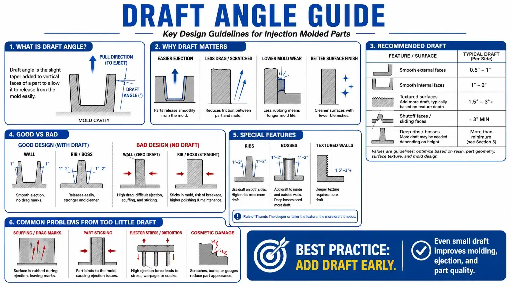
A draft angle is a small taper on the vertical walls of a part. It lets the part release cleanly from the mold. Without that taper, plastic grips the steel as it cools and shrinks. Then ejection turns into a fight.
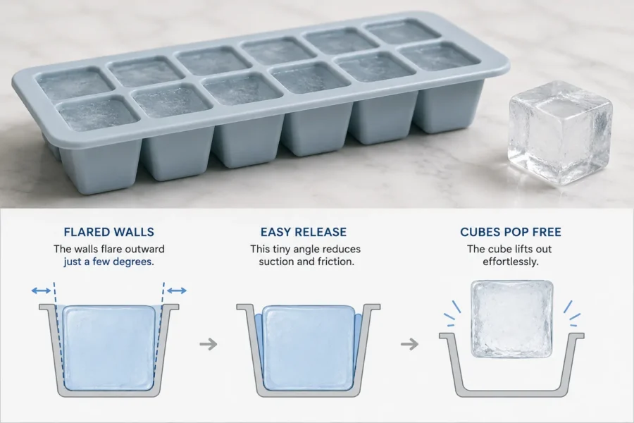
Think of an ice cube tray. The walls flare outward a little. That tiny angle lets the cubes pop free. Molds work the same way. Any wall that runs along the direction the mold opens needs a few degrees of slope.
Draft is always measured against the pull direction — the direction the mold opens. A flat top facing the opening needs no draft. A side wall running along the pull does. Friction builds along its full height as the part travels off the steel.
Why Does Draft Angle Matter for Buyers?
Draft hits the three things buyers actually track: cost, lead time, and reject rate. Get it right and you’ll never notice. Get it wrong and it shows up as scrap, slower cycles, and tooling rework you pay for.
With correct draft, the molder runs faster cycles and the tool lasts longer. Surfaces stay clean. With too little draft, the supplier adds pins, hand-polishes the steel, or cuts more angle into a finished mold. Each one costs money. That cost lands in your next quote — or in your scrap reports.
What Happens Without Enough Draft?
Too little draft means drag marks, ejector pin push-through, stress whitening, and stuck parts. Scrap climbs. Tool life shortens. None of it is subtle on the shop floor.
Drag Marks & Scuffing
The part scrapes the steel during ejection. You see visible scratches running along the wall.
Ejector Pin Witness
High ejection force makes pins dimple the surface. In bad cases they punch through.
Stress Whitening & Deflection
Thin walls flex under ejection load. They distort or crack as the part comes off the core.
Stuck Parts & Downtime
A part that won’t release stalls the press. The operator pulls it by hand. Cycle time blows up.
Premature Tool Wear
High-friction ejection scores and polishes the cavity over time. Finish quality drops.
One problem feeds the next. Low draft raises ejection force. Higher force raises scrap. That’s why we treat draft as non-negotiable on every part we quote.
How Much Draft Angle Do Plastic Parts Need?
Most parts need 0.5° to 1° on standard exterior walls, 1° to 2° on deep interior surfaces, and as low as 0.25° on mirror walls. Textured and deep-draw surfaces need a lot more.
A common shop rule is about 1° per inch of wall depth. That’s a fine starting point for a rough check. The sharper engineering rule for textured surfaces comes below. Deeper draws build more friction, so they get more slope.
Draft Angle Guide: Recommended Values
Use this table to sanity-check a vendor’s DFM report before tooling starts.
| Feature / Surface | Suggested Draft | Notes |
|---|---|---|
| Mirror / high-gloss finish (SPI A-1) | 0.25° – 0.5° | Pair with a careful ejection layout. Lowest risk on a polished pull direction. |
| Polished side wall (SPI A-2) | 0.5° – 1° | Low friction. Safe default for smooth cosmetic walls. |
| Standard general exterior surface | 0.5° – 1° | Safe baseline for most parts. |
| Deep cavity / interior wall | 1° – 2° | Goes up with depth. Deeper features need more. |
| Rib side face | 0.5° – 1.5° | Per side. Add more for tall ribs. |
| Boss outer wall | 0.5° – 1.5° | Treat separately from the inner bore. |
| Boss inner bore | ~0.5° | Inner cores stick harder than outer walls. Always call this out on the drawing. |
| Light texture (matte / fine bead) | 1° – 3° | Apply the texture rule: 1° per 0.01 mm of grain depth. |
| Medium texture | 3° – 4° | Confirm the grain depth value with your texture vendor. |
| Heavy / leather grain | 4° – 6°+ | Coarse grains can run past 6°. Higher if the part shrinks onto the grain. |
| Snap-fit / living hinge | Case by case | Often local zero-draft zones. Document the reason. |
These ranges are common practice, not one industry rule. Deep walls, aggressive texture, or a high-shrink resin push you to the high end. A shallow polished part can sit at the low end.
How Does Surface Texture Change Draft Requirements?
Texture sharply increases the draft you need. The grain peaks interlock with the steel during ejection. Deeper grain means more taper — and the math is simple.
Real numbers: a leather grain at 0.08 mm depth adds about 8° on top of your baseline wall draft. A light bead-blast at 0.02–0.03 mm needs 2°–3° extra. A coarse grain at 0.05–0.08 mm wants 5°–8° or more in total.
This applies whether the plastic shrinks away from the grain or onto it. When it shrinks onto the grain, the required angle climbs higher. Talk to the graining vendor before mold construction starts.
How Does Material Affect Draft Angle?
Resins shrink and grip at different rates. High-shrink and rigid materials usually need more draft than soft, low-shrink ones.
| Resin Category | Examples | Draft Tendency | Reason |
|---|---|---|---|
| Semi-crystalline, high shrink | PP, PE, unfilled PA66 | Higher draft needed | The dense crystalline phase clamps onto cores as it solidifies. |
| Glass-filled rigid | PA66-GF, PBT-GF | Higher draft needed | Fiber alignment causes anisotropic shrinkage and differential stress. |
| Amorphous, standard | ABS, PC, PC/ABS, PMMA | Standard range | Gradual glass-transition solidification. 0.5°–1° baseline holds up. |
| Flexible / elastomeric | TPE, TPU | Sometimes less | The part can flex off the steel. Tacky grades still need real draft. |
Always pair material choice with finish and wall depth. A high-shrink resin on a deep textured wall is the worst case on the bench. You need the full baseline draft plus the full texture allowance.
How Does Draft Prevent Part Deflection and Warpage?
Enough draft lowers ejection force. Lower force means thin or tall walls don’t bend, twist, or hold permanent warpage.
Deflection happens in two stages. First, a part that clings to the core forces ejector pins to push hard at a small footprint. Thin walls bow inward. Ribs lean. Flat surfaces curl a little. The plastic is still warm at ejection. So that temporary bend can lock in as permanent warpage once the part cools fully.
Draft cuts the grip between plastic and steel. The part releases with gentle force spread across the wall — not concentrated force at the pins. Less localized stress. Walls stay straight. Dimensions stay stable.
How Do Ribs, Bosses, and Deep Cores Affect Draft?
Ribs, bosses, and deep cores are tall narrow walls. They build heavy friction during ejection. These are the features that fail first when draft is marginal. Spec them separately from the main walls.
Ribs
Use 0.5° to 1.5° per side. Add more for tall ribs. Other rib geometry rules:
| Rib Parameter | Recommended Value | Purpose |
|---|---|---|
| Rib thickness | 40%–60% of nominal wall | Prevents sink on the opposite face. |
| Rib height | ≤ 2.5–3× base wall | Controls ejection friction and warpage risk. |
| Rib spacing | ≥ 2× wall thickness | Allows proper cooling between ribs. |
| Root radius | R ≈ 0.25–0.4× wall | Cuts stress concentration and aids flow. |
| Draft per side | 0.5° – 1.5° | Goes up with rib height. |
Bosses
Treat the outer wall and the inner bore separately. The inner core forming the screw hole has plastic on all sides. It sticks harder than anything else on a typical part.
| Boss Parameter | Recommended Value | Notes |
|---|---|---|
| Outer wall thickness | 40%–60% of surrounding wall | Prevents sink on the adjacent surface. |
| Outer wall draft | 0.5° – 1.5° | Standard wall draft range. |
| Inner bore draft | ~0.5° | Always call this out. Drawings often skip it. |
| Root radius | R ≈ 0.25× wall | Reduces sink and stress cracking. |
Deep Cores
The deeper the core, the more draft you need — often 2° or more. Deep cores trap heat and run hotter than shallow features. Hotter cores raise local shrinkage and grip. Any core approaching a 1:1 depth-to-width ratio needs review for both draft and dedicated cooling (a baffle or bubbler).
How Do You Measure and Specify Draft on a Drawing?
Draft is measured in degrees from the pull direction. Call it out clearly on the drawing or model. Vague draft callouts cause real disputes at T1.
- State the pull direction clearly so everyone knows which walls need draft.
- Build draft into the CAD model instead of expecting the molder to add it. Modeled draft kills guesswork and locks the tolerance stack before steel is cut.
- Note the minimum acceptable draft on critical walls. Flag any zero-draft zones with a documented reason.
- Reference the texture standard by grain number and depth in mm. The molder can then back-calculate from the 1°/0.01 mm rule.
- Confirm draft in the DFM report before the mold is cut. DFM is your last cheap chance to add draft.
Can a Part Have Zero Draft?
Yes, but only with special handling. Zero-draft walls need mirror-polished steel in the pull direction. They need careful ejection engineering. They raise tooling cost and production risk.
Molders pull off zero draft with mirror polishing along the pull direction, lifters, or extra ejection support. These work. They also add tooling cost, slow the cycle, and shorten tool life. Zero draft on grained surfaces is basically impossible in production. The grain peaks mechanically interlock — there’s no taper to break them free.
Draft Angle vs. Wall Thickness vs. Radii
Draft, wall thickness, and radii are the three moldability levers. They work together. Fixing one alone rarely saves a difficult part.
Draft Angle
Cuts grip between plastic and steel at demolding. Decides whether the part releases or fights the tool.
Wall Thickness
Uniform walls reduce differential shrinkage. Aim to vary no more than ±25% of nominal across the part.
Radii (Fillets)
Internal radii at R ≥ 0.25–0.5× wall cut stress at feature roots and improve melt flow.
Uniform walls cut differential shrinkage. That cuts warpage — the same warpage draft helps prevent. Generous internal radii improve flow and reduce stress, which complements clean ejection. Address all three together during DFM. Not one at a time.
How to Review a Quote for Draft Problems
You don’t need to be a molding engineer to catch draft issues. A short question list before tooling approval handles most of them.
- Does the DFM report cover draft on vertical walls, interior walls, and deep cavities separately?
- Are deep ribs, bosses, and core bores given specific degree values — not just “adequate draft”?
- If textured, does the DFM show grain depth in mm and the resulting minimum draft?
- Are any zero-draft surfaces flagged with a documented reason in the design intent?
- Has the supplier flagged any wall as an ejection risk with a proposed fix?
- Is the pull direction stated and consistent with how the part actually works?
- For high-gloss or mirror finishes, is draft set at 0.25°–0.5° with a matching ejection plan?
Common Draft Angle Mistakes
Most draft mistakes come from designing for looks first and ejection second. They’re all avoidable at design review.
| Mistake | Consequence | Prevention |
|---|---|---|
| Adding texture after draft is locked | Too little taper for the grain depth. Parts drag or stick. | Confirm texture standard and grain depth before DFM sign-off. |
| Forgetting draft on rib faces and boss bores | Sticking features. Ejector pin damage. | Review every feature type separately in the DFM checklist. |
| Using one draft value for the whole part | Over- or under-drafted features on the same part. | Zone the draft by surface type and feature depth. |
| Calling out zero draft on cosmetic walls | High polish cost, slower cycles, shorter tool life. | Document the functional reason. Look at lifters or alternative ejection first. |
| Rib thickness above 60% of nominal wall | Sink marks on the opposite face. Adds ejection stress. | Hold rib thickness at 40%–60% of the adjacent wall. |
| Choosing coarse texture late in design | Draft relief cuts in finished cavity steel — costly. | Spec texture before the mold is cut. Recalculate draft from grain depth. |
Frequently Asked Questions
What is the minimum draft angle for injection molded parts?
A common minimum is 0.25° to 0.5°. That applies to mirror-finish, shallow walls with a careful ejection layout. For standard smooth walls, 0.5° to 1° is a safer default. The real minimum depends on wall depth, resin, surface finish, and part geometry. Check with your molder and your resin supplier’s datasheet.
Does more draft angle weaken the part?
Usually no. A few degrees of taper rarely changes function. It does noticeably improve ejection. The trade-off is a slight change in wall geometry at the feature edge. Engineers should account for it on critical fits and sealing surfaces.
How does draft angle affect mold cost?
Correct draft tends to lower total cost. It cuts scrap, ejector complexity, and tool wear. Zero-draft or under-drafted designs raise cost. They need polished steel, lifters, or extra ejection support. They also shorten tool life because ejection friction goes up.
Is draft the same for the inside and outside of a part?
Not always. Inner walls and bore surfaces often need equal or slightly more draft than outer walls. Plastic shrinks onto internal cores. Standard guidance is about 0.5° on boss bores and 1° to 2° on deep interior cavity walls. Compare that to 0.5° to 1° on standard exterior walls.
Can draft fix warpage by itself?
No. Draft cuts ejection-related deflection. Warpage also depends on wall thickness uniformity, cooling balance, gate location, and material shrinkage anisotropy. That last one matters most in glass-filled resins. Draft is one factor among several. It works best inside a balanced DFM approach.
How does the texture grain depth rule work in practice?
The rule is 1° of draft per 0.01 mm of grain depth. A texture at 0.06 mm depth needs about 6° of draft from the texture alone. That’s on top of the baseline draft for the wall type. Get the exact grain depth from the texture vendor. Catalogue estimates can vary. Any deviation needs to be agreed with the graining specialist before mold construction.
Who decides the draft angle — the buyer or the supplier?
Both, ideally during DFM. The designer sets intent and constraints. The molder confirms feasibility and proposes specific values in the DFM report. A good supplier flags any wall where their proposed draft creates an ejection risk. The buyer then approves the solution before tooling spend is committed.
Conclusion
Draft angle is a small design detail with a huge effect on quality, cost, and lead time. Standard exterior walls usually want 0.5° to 1°. Deep interior features want 1° to 2°. Textured surfaces add draft at 1° per 0.01 mm of grain depth. Mirror finishes can go as low as 0.25° with a careful ejection plan.
For buyers, the takeaway is simple. Make draft a checkpoint at every stage. Confirm texture and grain depth before tooling. Insist on a DFM report that addresses every wall type with specific degree values. Treat any zero-draft surface as a documented cost decision. A supplier who reviews draft before cutting steel saves you scrap, rework, and delay down the line.