Here’s a practical DFM (Design for Manufacturability) check list for injection mold design you can run before quoting / steel cutting. I’m writing it like a shop-floor checklist (pass/fail + numbers).
1) Part basics (must lock first)
- Material, shrink rate, filled % confirmed (supplier + grade).
- Target appearance standard (A/B/C surfaces) and defect acceptance (sink, weld lines, gate blush, flow marks).
- Annual volume + cavitation target (1, 2, 4, 8… cavities) and machine tonnage estimate.
- Nominal wall thickness defined, with min/max tolerance.
2) Wall thickness & geometry
- Keep uniform wall: aim ±10–15% variation across the part.
- Typical nominal wall (rule-of-thumb):
- PP/PE: 1.2–2.5 mm
- ABS/PC: 1.5–3.0 mm
- PA/PA66: 1.0–3.0 mm (filled needs more attention)
- Thick sections: core out to avoid sink; use gradual transitions with radius not steps.
- Corner radii: inside radius ≥ 0.5× wall, outside radius = inside + wall.
3) Draft angles (release + cosmetics)
- Minimum draft (general): 1° per side.
- Textured surfaces: add +1° to +3° depending on texture depth.
- Deep ribs/bosses/features: 0.5°–1° minimum if space is tight, but expect higher ejection force.
- Any “no-draft” cosmetic wall = flag as high risk.
4) Ribs, gussets, bosses
- Rib thickness: 0.4–0.6× nominal wall (to avoid sink).
- Rib height: ≤ 2.5–3× wall (higher = fill/warp risk).
- Rib root radius: ≥ 0.25× wall.
- Boss OD: keep wall around boss ≤ 60% of nominal; core it out.
- Screw bosses: check pilot hole, thread engagement, and crack risk (esp. PC/PA).
5) Holes, slots, shutoffs
- Through-hole core pin: length/diameter (L/D) risk:
- Steel core pin L/D > 10 = deflection/breakage risk (flag).
- Thin shutoff land: avoid knife edges; keep shutoff ≥ 0.5–1.0 mm robust where possible.
- Side holes/undercuts: confirm if slides/lifters needed and whether part can tolerate witness lines.
6) Undercuts & parting line strategy
- Identify all undercuts early; define: no action / hand-load insert / lifter / slide / unscrew.
- Parting line must avoid key cosmetic faces where possible.
- Confirm steel-safe areas (where you can add steel later).
7) Gate & runner concept (fill, cosmetics, strength)
- Gate type choice aligned with: appearance, weld line location, vestige limit, cycle time.
- Gate location rules:
- Gate into thicker region when possible.
- Avoid gating into thin long flow paths without venting.
- Avoid weld line across high-stress zones.
- Vestige requirement (e.g., “≤0.2 mm”) must be stated.
- For multi-cavity: runner balance concept (naturally balanced preferred).
8) Venting (most missed DFM item)
- Ensure vents at end-of-fill, ribs, pin bosses, and knit line zones.
- Typical vent depth (ballpark; varies by resin): 0.02–0.05 mm with adequate land + exhaust.
- Add overflow / vent features if burn risk is high.
9) Ejection (marks, sticking, deformation)
- Confirm ejection on non-cosmetic faces.
- Ejector pin count/size adequate to avoid “banana” bending.
- Add strippers / sleeves / blade ejectors where pins would mark or punch through.
- Check deep cores: add air poppet or better draft.
10) Cooling & warpage risk
- Thick sections + asymmetry = warpage risk (flag).
- Cooling feasibility: can you cool close enough to hot spots (boss fields, thick ribs)?
- If flatness is critical: require a warpage simulation (Moldflow / Cadmould) or at least a cooling review.
11) Tolerances & metrology reality
- Call out only what matters: tight tolerances drive cost.
- Typical molding tolerance (rule-of-thumb): ±0.05–0.2 mm depending on size/material/process.
- GD&T only where functional; avoid stacking “tight everywhere”.
12) Mold build details (tooling DFM)
- Steel selection (P20 / H13 / S136 etc.) aligned with resin (glass-filled = wear).
- Surface finish spec (SPI A/B/C) + texture IDs.
- Wear inserts in high-abrasion zones (filled nylon / glass).
- Serviceability: can you replace gate insert, slides, lifters quickly?
13) Sampling & documentation (avoid disputes)
- Define deliverables:
- T0/T1 sample plan
- First Article Inspection (FAI) dimensions list
- CPK/PPK requirements if any
- Appearance approval method (lighting + distance)
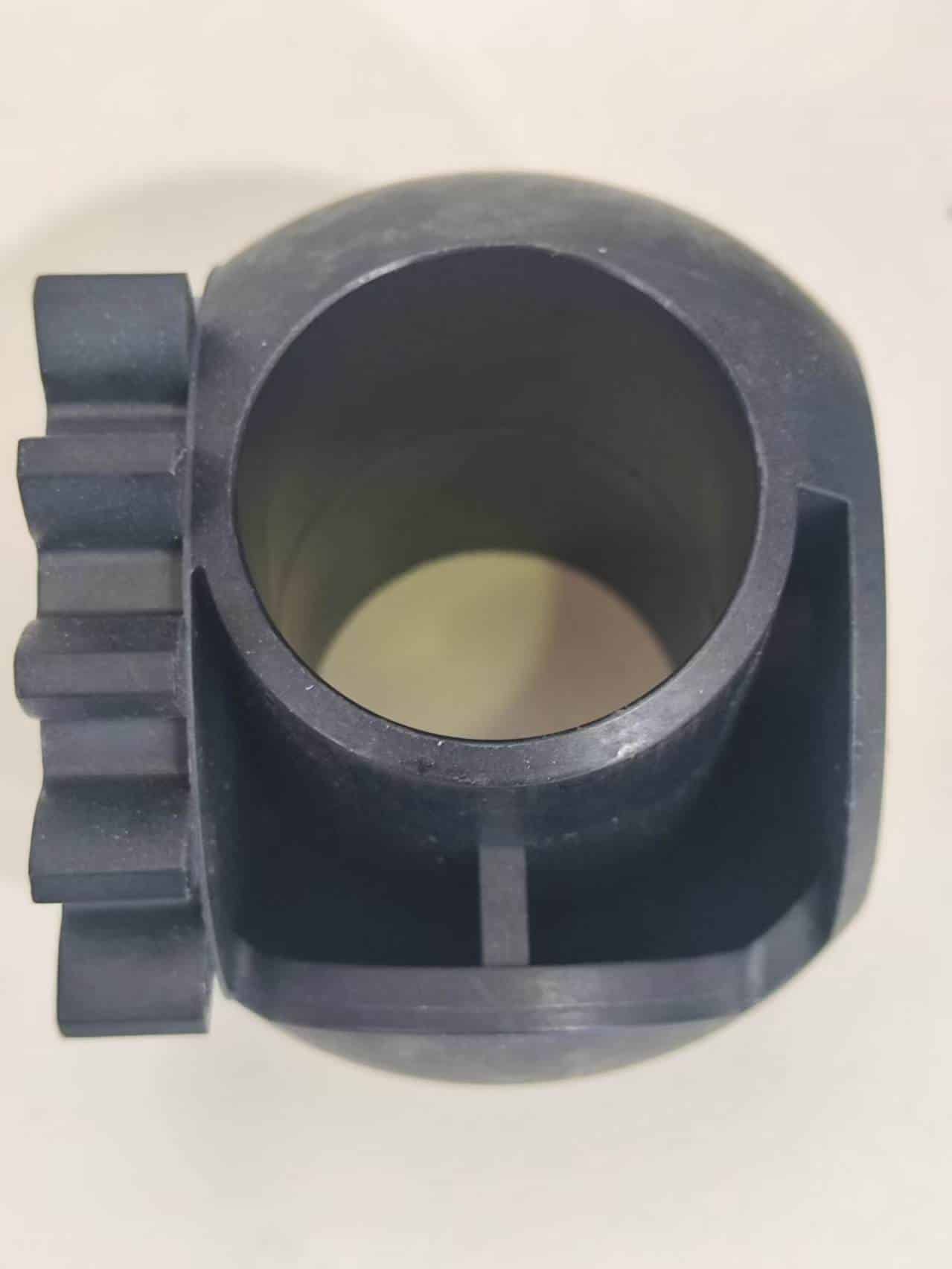
DFM Check — Injection Mold Design (ABS, 2.5 mm Wall)
Deep cylindrical cavity + base ring + side “teeth” feature. Key risks are sink at thickness transitions, draft for release, venting at end-of-fill, and stable ejection to avoid whitening.
Material: ABS
Nominal wall: 2.5 mm
Primary risk: sink + drag marks
Primary need: draft + venting + balanced ejection
1) Wall Thickness & Sink Control
- 2.5 mm is a good nominal wall for ABS, but thickness stacking at the cylinder-to-base transition can create sink and internal stress.
- Prefer coring-out thick areas and using ribs instead of solid mass.
- Rib thickness: 0.5–0.6 × 2.5 = 1.25–1.5 mm.
- Rib height: keep ≤ 3× wall (≤ 7.5 mm) unless draft/ejection is improved.
- Corner radii: inside radius ≥ 0.5× wall (≥ 1.25 mm); outside radius = inside + wall.
2) Draft Angles (Release & Cosmetics)
- Inner cylinder draft: ≥ 1.0° per side (more if the cavity is deep).
- Outer walls: 0.5–1.0° per side.
- Side “teeth” faces: ≥ 1.0° to avoid drag marks / scuffing.
- If textured, add +1° to +3° depending on texture depth.
3) Parting Line & Undercut Check
- Cost-friendly approach: parting line around the base ring; cylinder formed by a central core (often on the moving side for easier ejection).
- Verify whether the “teeth” geometry creates an undercut in the opening direction.
- If any undercut exists, plan for slide / lifter (tool cost and lead time increase).
- Rule: if the feature “shadows” material in the mold opening direction, it’s an undercut.
4) Gate & Runner Concept
- Prefer gating into the base ring (edge gate / fan gate) to fill upward and reduce cosmetic risk at the top opening.
- If appearance needs a smaller vestige, consider a submarine (tunnel) gate from the base side.
- Avoid gating near the cylinder opening (higher risk of flow marks / jetting and harder venting).
- Confirm acceptable gate vestige (example: ≤ 0.2 mm) before cutting steel.
5) Venting (Critical for Deep Cavities)
- Add vents at end-of-fill areas: cylinder top edge, far ends of the base ring, and around the “teeth” feature.
- Typical ABS vent depth (shop range): 0.02–0.05 mm with proper land and exhaust path.
- Consider overflow/vent pockets if burn marks appear during trials.
6) Ejection Strategy (Prevent Whitening / Ovality)
- For a deep cylinder, use sleeve ejection or a stripper ring where possible for even release.
- Place pins on non-cosmetic faces and avoid thin ribs near the root (pin push-through risk).
- Deep cores may benefit from air poppet assist to reduce sticking.
