Injection molded plastic electronics components & plastic mold manufacturer
Injection Molded Plastic Electronics Components & Plastic Mold Manufacturer
Optimieren Sie die Herstellung von Elektronik- und Elektrokomponenten mit unseren spezialisierten Kunststoffformen. Wir bieten präzisionsgefertigte Spritzgussformen für die Großserienproduktion von hochwertigen Kunststoffteilen für Elektronik, elektrische Steuerungen, Steckverbinder, Gehäuse und mehr.
Unsere umfangreiche Formenkollektion ermöglicht die Herstellung von isolierte Draht- und Kabelspulen, Schutzschaltergehäuse, Steckdosenabdeckungen, Schalterplatten, Rohrverschraubungenund zahllose andere Kunststoffteile, die für elektrische Systeme unerlässlich sind. Wir bieten auch Formen für Unterteilungsblöcke, Kabelbinder, Drahtverbinder und andere Spritzgussteile.
Unsere aus hochwertigem Stahl gefertigten und hervorragend bearbeiteten Formen bieten unschlagbare Haltbarkeit und Maßgenauigkeit für gleichbleibende Produktionsergebnisse. Unsere fachkundigen Formenkonstrukteure optimieren die Konstruktionen für schnelle Zykluszeiten, niedrige Ausschussraten und reduzierte Herstellungskosten.
Mit Kapazitäten für Mehrkavitätenwerkzeuge, Zweikomponenten-Spritzguss, gasunterstütztes Spritzgießen und andere fortschrittliche Techniken bieten wir die ideale Werkzeuglösung für Ihre spezifische Anwendung. Verlassen Sie sich auf unsere langjährige Erfahrung im Elektro- und Elektronikformenbau, um die Effizienz zu steigern.
What We Mold for Electronics & Electrical Systems
- Connectors & housings: connector shells, wire connectors, terminal covers
- Enclosures: control boxes, sensor housings, small device shells
- Electrical accessories: outlet covers, switch plates, conduit fittings
- Production parts: cable spools, cable ties, subdivision blocks
Injection Molded Electronics Components: Design Complexity & Cost
The moulded consumer electronics components made from injection may be intricate or simple. Intricate plastic electronic components molding can be economical because they may combine many parts into one piece and thus save the cost of the fabrication and joining of several separate pieces. Joints must be machined and bolted together. Misalignment and loosening during vibration may result. Sand castings weighing several tons (such as a locomotive frame) have been made to advantage because of their ability to combine several parts into one piece.
Je komplizierter die gegossene Elektronikkomponenten, the more ingenuity and control required. The simpler the electronics components, the less the cost of plastic mold and pattern equipment and hence the less expensive the electronics components. Variations in size and strength may be more difficult to control in more complex moulded electronics components; thus a more highly skilled molder may be required.

The design of the electronics components to be moulded depend upon the behavior of the plastic material as it cools, the construction of the mold, and the functions of the part in service. The art of molding has progressed to such an extent that practically anything can be moulded that is within the size of the equipment available. It may not be economical to mould the part today, but in a few years the process may be improved so that it may be economical to redesign the part from a sheet metal or welded design into a injection moulded electronic part. To make a moulded component simple and easy demands the highest skill and the best judgment on the electronic component of the designer and mold maker.
Plastic molding processes use a mold into which a melted fluid plastic material enters and is cooled. On solidification, the material takes the shape of the electronic component mold cavity. The liquid or highly plastic state of the material when moulding distinguishes it from die-forging or extrusion processes in which the material is shaped only in a plastic condition under high pressures. In the latter instances, the metal has received mechanical working treatments; while in the former, it has not.
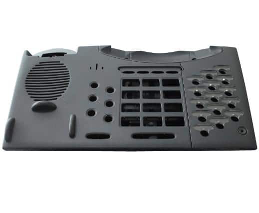
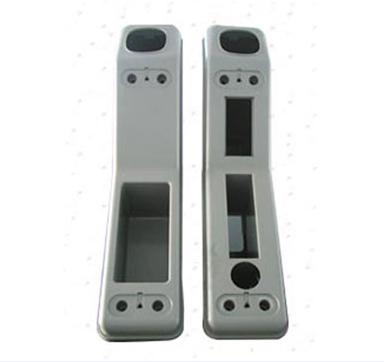
Injection Molding Photos


Injection Moulding Processes: Four Main Elements
- das Muster,
- die Form und die Kerne,
- the part,
- das Material.
WAS UNSERE KUNDEN SAGEN


MATERIAL
Alloy groups being used as plastic moulding include the following:
1. Eisenhaltig
- a. Gusseisen (einfach)
(legiert [Cr, Ni, Mo, und andere])(weiß) - b. Verformbares und perlitisches verformbares Eisen (unlegiert und legiert)
- c. Stähle (Kohlenstoff [niedrig-mittel-hoch])
(Legierung [niedrig-mittel-hoch])(hitze- und korrosionsbeständig [Fe-Cr, Fe-Cr-Ni])
2. Nichteisenmetalle
- a. Aluminiumbasislegierungen (leicht und einfach zu bearbeiten)
- b. Magnesium-Basis-Legierungen
- c. Kupferbasislegierungen (hart und kühlend)
- d. Nickel-Basis-Legierungen (Ni-Mo-Fe, Ni-Mo-Cr-Fe)
- e. Blei-Basis-Legierungen
- f. Zinn-Basis-Legierungen
- g. Titan-Basis-Legierungen
- h. Zink-Basis-Legierungen
3. Hitze- und korrosionsbeständige Legierungen
- a. Kobalt-Basis-Legierungen (Stellit, Vitallium)
- b. Chrom-Basis-Legierungen
The injection temperature of the melt plastic and finish required determine the type of mould and the material used to make the moulds. It is necessary to control injection temperatures within a close range to get constant results.
Some materials are viscous and do not flow easily into the moulds, especially if they are cooled slightly on striking the surface of the mould. The metals are heavy with respect to the nonmetallic mould materials;
if they flow too rapidly, they will wash the moulds and pick up foreign material. The heavy liquid can float the cores as well as the cope as the metal enters the mould. This causes shifts in cores and distortion of the mould.
Weights on the moulds and clamps are used to counteract this liquid pressure. A feeder 1 foot high for a typical ferrous material will exert 4 psi on a core. If the core has a face area of 5 x 8 inches, the force exerted to shift it out of place would be 160 lbs. The heavy, hot fluid material must be guided to its place without damage to the mould or contamination of the material. This mass of hot molten or solid plastic material has no strength at temperatures above and near the melting point. Therefore, the plastic mould and cores must support the material until it cools to the point where it is strong enough to carry its own weight.
ERSTARRUNG
Da die heißes Kunststoffmaterial kühlt abEs zieht sich im flüssigen Zustand, bei der Verfestigung und im festen Zustand zusammen. Diese Verringerung des Volumens may amount to from 2 to 15 per cent depending on the material. (Some materials do not shrink during solidification, namely bismuth and gallium.)
- ABS 0,3~0,8 2
- HDPE 2~5.0 10
- HIPS 0,2~0,6
- HPVC 0,6~1,0 12
- LCP 0,006
- LDPE 1,5~5,0 14
- PA6 0,6~1,4 16
- PA6+30%GF 0,3~0,7 17
- PA66 0,8~1,5
- PA66+30%GF 0,2~0,8
- PASF 0,8
- PBT 0,44
- PBT+30%GF 0,2
- PC 0,5
- PC+30%GF 0,2
- PET+30%GF 0,2~0,9
- PMMA 0,2~0,8 34
- POM 1,5~3,5 35
- POM+25%GF
- PP 1~2,5 38
- PP+30%GF 0,4~0,8
- PPS+40%GF <0,12
- PS 0,4~0,7
The contraction must not be restricted while the material is weak or it will tear apart or crack; therefore, moulds and cores must give or release under the pressure. As the fluid material strikes the surface of the mould, it cools and a thin layer of material solidifies, followed by the progressive dendritic growth until the whole section is solid. If the sections are uniform in thickness, the section tends to be a homogeneous solid.
The non-directional properties of moulding are associated with the random distribution of metal crystals and dendrites developed during freezing. Directional orientations of dendrites and the effect of fibering on properties can be obtained in an improperly designed moulding. Non-directionality of properties is a distinct advantage of moulding. If the section is larger at certain points, and the cooled layers on the outside cannot contract as the center cools, voids will occur because there is no material to fill the space. This condition requires feeders to feed molten or viscous material into these areas while the material is solidifying.
Die Erstarrungsgeschwindigkeit beträgt:
- (1) directly proportional to the rate of heat transfer through the mold walls,
- (2) directly proportional to the surface area,
- (3) umgekehrt proportional zur Gussmasse.
These three factors illustrate the relations between solidification of metallic alloys and moulded shape and size. Since there is little variation in the rate of heat transfer through the mould walls, the most important relationship lies in the surface-area-volume ratio.
A relatively large dendrite grain size may be developed in the process of solidification as a result of the freezing rate or section size of the plastic moulding. Large castings and ingots freeze with coarse grains. Thin-sectioned castings, or castings made in metal moulds, develop a fine-grain size due to rapid freezing. Normally, a fine-grain size is desirable since higher ductility and impact strength values are obtained at a given tensile strength level.
Heiße oder weiche Flecken
Hot or soft spots are the last portions of the injection molding to solidify. They usually occur at points where one section joins another, or where a section is heavier than that adjoining it—at a square corner for instance. The outside of the corner should be rounded to reduce the section change.
Electronics Injection Molding FAQ
Q1: What electronics parts are best suited for injection molding?
Connectors, housings, enclosures, brackets, cable accessories, and high-volume components with repeatable geometry are typically ideal. Material, wall thickness, and cosmetic requirements determine the best strategy.
Q2: Can you build multi-cavity molds for electronics components?
Yes. Multi-cavity tooling is common for small parts like connectors and caps. We design for balanced filling, stable ejection, and consistent dimensions across cavities.
Q3: What documents should I send for a fast quote?
STEP/IGES 3D file, key 2D dimensions/tolerances, material and color, surface/cosmetic definition (A/B/C), annual volume, and any critical assembly interfaces.
Q4: Do you support insert molding or two-shot molding?
We can support insert molding and advanced processes depending on part structure and volume. Share your design and requirements so we can confirm feasibility and tooling approach.
