7 Costly Reasons Why Uniform Wall Thickness Matters in Injection Molding
Why Uniform Wall Thickness Matters in Injection Molding: cut defects, tame warpage, and lower your price per part. A buyer’s guide.
Wall thickness rarely shows up on your PO. But it quietly drives your reject rate, your unit price, and your ship date. Knowing why uniform wall thickness matters in injection molding lets you flag a risky design before steel is cut. It also hands you the right questions for suppliers. Most quotes we review skip this conversation entirely. That’s where the expensive surprises hide. This guide explains the principle in plain terms. It walks through the defects uneven walls create. Then it gives you a real checklist for judging quotes and parts.
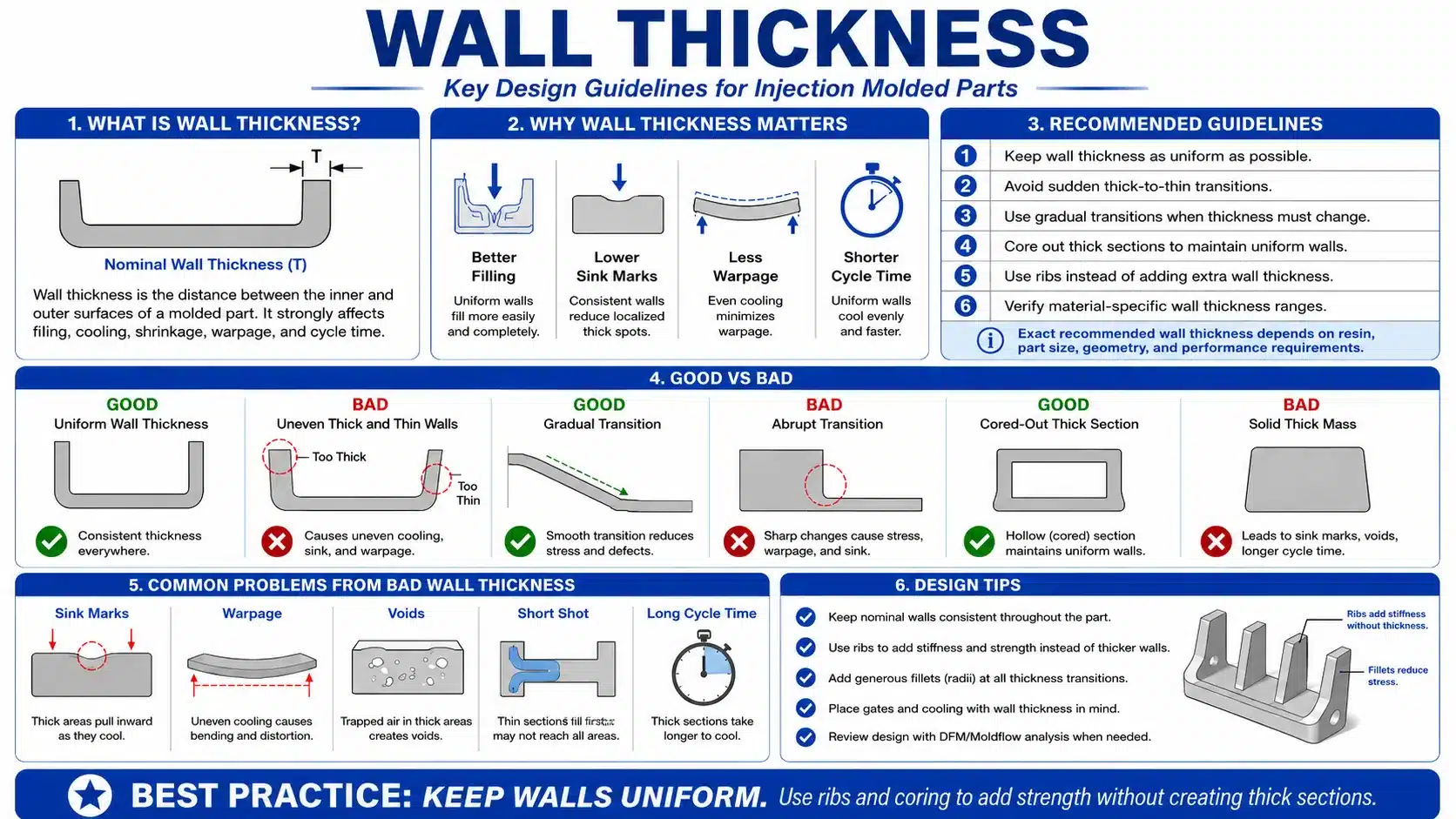
What Is Uniform Wall Thickness in Injection Molding?
Uniform wall thickness means the walls stay close to one nominal value across the whole part. A part with a 2.5 mm wall everywhere is uniform. A part that jumps from 1.5 mm to 4 mm is not.
The “wall” is the structural shell. Most molded parts are hollow shells, not solid blocks. The nominal wall is the baseline thickness the designer picks first. Ribs, bosses, and every other feature get sized off it.
Uniform doesn’t mean identical to the micron. It means controlled. Small, gradual changes are fine. Sudden, large jumps are the problem. The goal is simple. Let the melt fill, pack, and cool at a steady rate everywhere.
Design manuals say it plainly. “The ideal injection molded part has equal wall thickness.” Where you can’t avoid a mass concentration, sit it as close to the gate as possible. And keep the thickness gap small.
Why Uniform Wall Thickness Matters in Injection Molding
Uniform wall thickness controls how the plastic cools. And cooling controls quality, cost, and schedule. Even walls cool at a steady rate. The part shrinks predictably and holds its shape. Uneven walls force the part to fight itself as it solidifies. That fight shows up as defects and scrap.
Here are seven reasons this one design choice carries so much weight for a buyer.
Reduces Scrap
Even walls cut the risk of sink, voids, and warpage. Fewer parts fail inspection.
Cuts Cycle Time
The thickest section sets the cooling clock. Thinner, even walls let the mold open sooner.
Lowers Unit Cost
Faster cycles plus less resin drop your price per part. A double saving on every shot.
Improves Dimensional Stability
Even shrinkage holds tolerances. Assemblies fit together without rework.
Protects Tooling Investment
Catch wall problems before steel is cut. You skip costly mold rework and lost lead time.
Speeds Delivery
Fewer process trials and fewer rejects keep production on schedule.
Strengthens Supplier Conversations
Now you can challenge a risky design instead of paying for it later.
The Cooling Problem Behind Wall Thickness
Uneven cooling causes most wall-thickness defects. Plastic enters the mold as a melt. It then dumps heat into the steel. Thin sections lose heat fast. Thick sections hold heat far longer.
That gap matters because plastic shrinks as it cools. One area cools and shrinks while its neighbor is still hot and soft. The part builds internal stress as a result. That stress shows up as warped shapes, pulled-in surfaces, and hidden weak spots.
Every 1°C rise in mold cavity temp adds about 2% to cooling time. Every 1°C drop in ejection temp adds about 2% too. Uneven walls compound this. A thick section forces a higher effective mold temp for the whole part. That inflates cycle time across the board.
How Uneven Walls Cause Warpage and Deflection
Uneven walls warp parts because different areas shrink by different amounts at different times. Warpage is the part bending or twisting after ejection. It’s the most visible result of differential shrinkage.
Deflection shows up two different ways. Keep them straight.
| Type | When It Occurs | Cause | Visibility |
|---|---|---|---|
| Molding deflection (warpage) | At and after ejection | Residual stress from uneven cooling and differential shrinkage | Flat lid bows; long rail twists; no load needed |
| In-service deflection | During use under load | Not enough stiffness for the applied force | Clip flexes; housing sags; load-dependent |
These two are tied together by a common design trap. A designer thickens a wall to fight in-service deflection. But that thicker wall now cools unevenly. So it warps coming out of the mold. The “fix” creates a new defect. We’ve pulled plenty of bowed lids off the press for exactly this reason. The right answer is to add stiffness through geometry, not mass. See Section 7.
Crystalline resins (PP, PA, POM, PBT) lose much more specific volume as they solidify than amorphous ones (ABS, PC, PS). So they shrink more overall. They’re also far more sensitive to wall variation. Non-uniform shrinkage from uneven walls is a major cause of warpage in unreinforced crystalline thermoplastics. That’s well documented in the engineering literature.
What Defects Come From Non-Uniform Walls?
Non-uniform walls produce a predictable family of defects. Once you can name them on a sample part, you know where the real problem sits. Design or process.
Sink Marks
Shallow dimples on the surface, usually opposite a thick feature. The thick section keeps shrinking as its core cools. That pulls the outer skin inward. A cosmetic and quality red flag.
Warpage & Twisting
Differential shrinkage bends or twists the part. Flat surfaces dome. Long parts bow. You get assembly gaps, misalignment, and fit failures.
Internal Voids
In thick sections, the outer skin freezes first. The trapped molten core shrinks and pulls apart. That leaves a vacuum void inside. It weakens the part and hides until you section it.
Short Shots
Thin sections can freeze before the melt fills them. The part comes out incomplete. A thin wall beside a thick wall gets starved of pressure as melt chases the easy path.
Weld Lines
When melt flows around features at uneven rates, the flow fronts meet and leave a weld line. Weak spot. Visible blemish. Worst in stress-bearing areas.
Residual Stress Cracking
Sharp transitions and thick-thin junctions concentrate molded-in stress. Gate areas, corners, and abrupt flow changes are the worst spots. These cracks often show up weeks after the part ships.
Most of these trace back to one root cause. Walls cooling at different rates produce non-uniform shrinkage and residual stress.
How Does Wall Thickness Affect Cycle Time and Cost?
Wall thickness affects cost because it sets cooling time. Cooling time runs 50–70% of the full molding cycle. That’s the single largest phase. The thickest section in a part decides how long the mold stays closed before ejection.
For a buyer, the math is simple:
- A thicker wall means a longer cycle.
- A longer cycle means fewer parts per hour.
- Fewer parts per hour means a higher price per part.
- Thicker walls also burn more resin per shot. So material cost climbs on top of machine-time cost.
A 254 × 254 mm polycarbonate plate without ribs at 2.5 mm wall had an in-mold cooling time of 10 seconds. The redesign — 1.5 mm wall with ribs — met the same deflection requirement at only 4 seconds cooling time. It used 20% less material by volume. Total system cost dropped to 73% of the solid-wall baseline. Ribs delivered a thinner nominal wall, shorter cooling, less material, and lower cost. All at once.
This is why thinning and evening out walls is one of the highest-leverage cost cuts in plastics. If a supplier suggests a wall reduction in design review, treat it as real savings. Not a corner cut.
How Does Wall Thickness Influence Strength and Deflection?
Wall thickness influences strength. But it isn’t the only lever, and often not the best one. Stiffness leans heavily on shape, not just thickness. A flat panel is floppy. The same panel with shallow ribs is far stiffer at the same wall. Stiffness scales hard with depth of cross-section. Geometry beats mass.
Designers raise stiffness while keeping walls uniform by using:
- Ribs to add depth without thickening the main wall.
- Gussets to reinforce corners and boss bases.
- Curves, domes, and flanges that resist bending through shape.
- Edge returns and lips that stiffen open panels.
If a quote leans on thick walls to hit a strength target, push back. Ask whether ribs or geometry could deliver the same stiffness for less. The data is clear. Ribs cut material 20% and dropped cooling from 10 to 4 seconds versus the thick-wall version. All at 73% of total system cost. A capable supplier already thinks this way.
What Are the Recommended Wall Thickness Ranges by Material?
Recommended wall thickness depends on the polymer. Each resin flows and cools differently. The values below are commonly cited nominal design ranges. Treat them as starting points, not hard limits. Your specific grade, geometry, and flow length still need validation with your molder and the material datasheet.
| Material | Common Name | Nominal Wall Range | Notes |
|---|---|---|---|
| ABS | ABS | 1.2 – 3.5 mm | General-purpose. Good flow. |
| PP | Polypropylene | 1.2 – 3.0 mm | Semi-crystalline. Higher warpage sensitivity. |
| PE | Polyethylene | 0.9 – 4.0 mm | LD/HD variants differ. Check the grade datasheet. |
| PS | Polystyrene | 0.9 – 4.0 mm | Amorphous. Low shrinkage anisotropy. |
| PC | Polycarbonate | 1.0 – 3.0 mm | Transparent parts: ~2.0 mm preferred. High mold temp needed (80–110°C). |
| PA | Nylon (PA6 / PA66) | 0.8 – 3.0 mm | Moisture absorption shifts dimensions. PA66 GF: 1.5–3.0 mm. |
| POM | Acetal | 0.8 – 3.0 mm | High-shrinkage crystalline. Tight wall uniformity matters most here. |
| PMMA | Acrylic | 0.8 – 4.0 mm | Optical parts. Stress cracking risk at the gate in thin walls. |
| PC/ABS | PC/ABS Blend | 1.5 – 3.0 mm | Lower bound sits higher than the individual resins. Drying is essential. |
Below the minimum, you risk short shots and incomplete fills. Above the maximum, you invite sink, voids, and long cycles. The exact sweet spot depends on flow length, geometry, and grade.
How Much Wall Thickness Variation Is Acceptable?
Keep wall variation within ±25% of the nominal wall across the same part. That’s the widely used DFM rule, backed by real shop-floor experience. Stay inside that band and fill, shrinkage, and dimensions all behave predictably.
Some sources cite ±10–15% as the limit. In practice, DFM experience puts the workable target at ±25% of nominal wall. Tighter rules make sense for optical or tight-tolerance parts. But applying ±10–15% everywhere builds over-constrained designs that are needlessly hard to mold. When in doubt, confirm with your molder against the actual material and geometry.
Two practical principles:
- Pick one nominal wall. Design everything back to it.
- When thickness must change, blend it gradually. Never step it abruptly.
See a large, abrupt thickness jump on a drawing? Flag it. It’s the most common avoidable cause of molding defects.
How Do You Transition Between Different Wall Thicknesses?
Transition between wall thicknesses with a gradual taper. Never an abrupt step. A common guideline ramps the change over a length of at least 3× the wall thickness. That gives a gentle slope instead of a sharp shoulder.
A smooth transition does three things:
- It evens out the cooling rate across the change. That cuts differential shrinkage.
- It lowers stress concentration at the junction. Engineering references flag sharp corners and thickness transitions as the highest molded-in stress zones.
- It keeps the melt flowing without hesitation. That prevents weld lines and short shots.
Coring is the other key tool. If a section has to be bulky for structural or functional reasons, hollow it out. We call this “coring” the part. The outer size stays the same. But the thick solid mass that would cause sink and voids is gone. Coring is one of the most reliable ways to keep walls uniform on complex parts.
How Do Ribs and Bosses Relate to Wall Thickness?
Ribs and bosses are the features most likely to break the uniform-wall rule. So they follow their own sizing rules tied to the nominal wall. Where a rib or boss meets the main wall, plastic piles up. That creates a local thick spot. It’s the classic source of sink marks.
| Feature | Recommended Ratio (of Nominal Wall) | Purpose | Risk if Oversized |
|---|---|---|---|
| Rib base thickness | 0.4 – 0.6 × wall | Balance stiffness vs. sink | Sink marks on the visible surface |
| Rib height | ≤ 2.5 – 3 × wall | Structural depth without fill issues | Short shot, flow hesitation |
| Rib spacing | ≥ 2 × wall | Allow cooling between ribs | Heat builds up. Sink shows between ribs. |
| Rib base fillet radius | R ≈ 0.25 – 0.4 × wall | Cut stress concentration at the base | Oversized R adds mass and causes sink |
| Boss outer wall | 0.4 – 0.6 × wall | Thin-wall boss avoids sink | Sink mark opposite the boss |
| Boss floor (base) thickness | 0.7 – 0.9 × wall | Support the boss without excess mass | Too thin: stress cracking. Too thick: sink. |
The principle is consistent. Every added feature respects the nominal wall and avoids a hidden thick region. When you review a part, look at the rib and boss junctions first. That’s exactly where sink shows up if these ratios were ignored.
Uniform Walls vs. Thick Walls: A Comparison
The table below sets the uniform thin-wall approach next to the over-thick approach. You can weigh the trade-offs at a glance.
| Factor | Uniform Thin Walls | Over-Thick / Uneven Walls |
|---|---|---|
| Cooling time | Shorter and even | Long. Dominated by thick spots. |
| Cycle time & output | Faster. More parts/hour. | Slower. Fewer parts/hour. |
| Material cost per part | Lower | Higher |
| Sink marks | Low risk | High risk |
| Warpage | Low risk | High risk |
| Internal voids | Low risk | Higher risk in thick zones |
| Dimensional stability | Strong | Weaker |
| Stiffness strategy | Ribs and geometry | Added mass |
| Overall unit cost | Lower | Higher |
What Should Buyers Ask a Molding Supplier?
Buyers protect themselves by asking wall-thickness questions before tooling. Run this checklist on every new quote or design. If your supplier can’t answer these, that’s your answer.
- Did you run a DFM (design for manufacturability) review on this part?
- Where are the thickest sections, and what is the wall variation across the part?
- Are there abrupt thickness transitions that should be blended with a taper?
- Are ribs and bosses sized to the 40–60% of nominal wall guideline?
- Could any walls be thinned or cored to cut cycle time and material cost?
- What is the predicted cooling time, and which feature drives it?
- Will you send a DFM report with issue locations and recommended fixes before cutting steel?
- Has a mold-flow simulation been run to check fill, shrinkage, and warpage?
A strong supplier welcomes these and answers with specifics. One who waves them away is a risk. The quality of that DFM conversation is one of your best early signals of a capable molder.
How DFM Analysis Catches Wall Thickness Problems Early
DFM analysis catches wall-thickness problems before they reach the mold. That’s when they’re cheapest to fix. A DFM review reads the 3D model and flags thick zones, abrupt transitions, mis-sized ribs, and likely sink or warpage spots.
Timing is the value. Changing a wall in CAD costs almost nothing. Changing it after steel is cut means mold rework, lost weeks, and renegotiated schedules. Simulation tools like Moldflow or Cadmould predict local shrinkage, warpage direction, and cooling time distribution before a single chip is machined. That turns a late, expensive surprise into an early, cheap edit.
- Specific locations of thick zones with dimensions
- Recommended fixes in plain language (e.g. “core out this boss to restore a 2.5 mm wall”)
- Transition lengths for any unavoidable thickness changes
- Predicted cooling time and which feature drives it
- Estimated impact on cycle time and cost if design changes are adopted
For buyers, requiring a DFM report as a condition of tooling approval is one of the simplest ways to protect quality, cost, and delivery in one step.
Frequently Asked Questions
What happens if wall thickness is not uniform?
The part cools unevenly. That drives warpage, sink marks, internal voids, and dimensional problems. Reject rates rise and cycle times stretch out. Most of it is avoidable with an even nominal wall and gradual transitions. Differential shrinkage from non-uniform walls is a documented major cause of warpage in unreinforced thermoplastics.
Can a part have more than one wall thickness?
Yes. Parts often need some variation to function. Keep changes within ±25% of the nominal wall wherever you can. Make transitions gradual, not abrupt. And core out bulky sections so the effective wall stays near nominal.
Does thinner wall thickness always mean a weaker part?
No. Stiffness comes mostly from cross-sectional depth and shape, not bulk. A thin wall reinforced with ribs can beat a thick flat wall. It cools faster and costs less to mold. Engineering data shows a ribbed thin-wall PC plate matched a solid plate’s deflection. It used 20% less material at 73% of system cost.
How does wall thickness affect part cost?
The thickest section sets cooling time. Cooling runs 50–70% of the total cycle. Cooling scales with the square of wall thickness (t ∝ h²). So doubling thickness roughly quadruples cooling. Thicker walls also use more material per shot. Over-designed walls raise cost on two fronts at once.
What is a sink mark and how is it caused by wall thickness?
A sink mark is a surface depression. It shows on the visible face opposite a thick feature like a rib or boss. The thick area cools and shrinks slower than the wall around it. That pulls the outer skin inward as it contracts. Keep rib and boss base thickness at 40–60% of the nominal wall. Most sink marks then disappear.
How can I reduce warpage on a molded part?
Even out the wall thickness. Stay within ±25% of nominal. Blend transitions with gradual tapers. Add ribs instead of thickening walls for stiffness. Run mold-flow simulation to find high-shrinkage zones before cutting steel. One caution: fiber-reinforced resins warp in the transverse direction from anisotropic shrinkage. That needs simulation to predict and design changes to manage.
Why do crystalline resins need stricter wall uniformity than amorphous resins?
Crystalline materials (PP, PA, POM, PBT) lose much more specific volume on solidification than amorphous ones (ABS, PC, PS). That means greater overall shrinkage. Any variation in wall thickness then creates proportionally larger gaps in local shrinkage. The result is more severe warpage in crystalline resins for the same wall variation.
What is the ±25% wall thickness guideline and where does it come from?
The ±25% guideline means the thinnest and thickest walls in one part should differ from nominal by no more than 25%. It comes from accumulated DFM experience in injection molding practice. Push past that range and differential shrinkage, warpage risk, and defect probability all climb sharply.
Why do molders care so much about cooling time?
Cooling takes 50–70% of the entire molding cycle. It’s the biggest single phase. So it controls how many parts a mold produces per hour. Uniform walls keep cooling short and consistent. That lowers cost and tightens part-to-part consistency. Every 1°C rise in mold temperature adds about 2% to cooling time. Wall thickness and temperature control are tightly linked.
Conclusion
Uniform wall thickness is one of the highest-leverage decisions in any molded part. It seldom appears in a contract. But even walls cool predictably, following a t ∝ h² relationship. They shrink consistently and hold their shape. That means fewer defects, faster cycles, lower cost, and on-time delivery. Uneven walls do the opposite. They invite sink, warpage, voids, and scrap. And they quietly inflate your unit price.
Key numbers to remember. Keep wall variation within ±25% of nominal. Hold rib and boss base thickness at 40–60% of the nominal wall. Ramp thickness changes over at least 3× the wall thickness. Treat cooling time as your primary cost driver. It dominates 50–70% of cycle time and scales with the square of thickness.
For a buyer, the practical message is simple. You don’t need to design the part. But you should recognize the risks, ask about thick sections and transitions, and insist on a DFM review before tooling. Treat stiffness as a geometry problem solved with ribs. Not a thickness problem solved with mass. Knowing why uniform wall thickness matters in injection molding turns you from a passive buyer into a partner. One who spots trouble early and steers the project toward better, cheaper, more reliable parts.