7 Proven Rib Design Rules for Stronger Injection Molded Parts (Avoid Costly Sink Marks)
Verified DFM proportions, corrected reference values, and a supplier checklist. So your ribs add stiffness, hold tolerances, and mold clean on the first shot.
Rib design rules for stronger injection molded parts decide one thing. Does your part hold shape under load, or does it warp and sink at first shot? Ribs buy you stiffness without thick walls. That means less material, shorter cycles, and parts that won’t drift on the inspection table. This guide gives you the numbers — rib thickness, height, draft, base radius, spacing — plus a verified reference table and the questions to put to a supplier before they cut steel.
What Are Ribs in Injection Molding?
A rib is a thin wall of plastic standing up from the part surface to add stiffness. Ribs work the same way as the bracing under a folding table. They carry load. The rest of the part stays thin.
Why bother? Because thick walls cause more trouble than they solve. A thick section cools slowly. Then come sink marks, internal voids, longer cycles, warpage. A rib targets stiffness where the load actually sits. The wall stays thin and stable.
Why Do Ribs Matter for Part Strength and Cost?
Ribs raise stiffness far more efficiently than thicker walls. Stiffness scales with the cube of section height. A tall rib adds big rigidity for little plastic. That’s the whole reason a well-ribbed part beats a flat thick one — lighter and stronger at the same time.
The flip side is brutal. An oversized rib leaves a thick base — and a thick base sinks. A rib that’s too tall fills poorly and traps gas. A rib without draft sticks in the tool and rips on ejection. Each mistake shows up as scrap, slower line speed, or a tool weld-up. We see all three on first-article runs from shops that skipped DFM.
Rib Design Rules for Stronger Injection Molded Parts: Core Ratios
All rib design comes down to five proportions, each tied to nominal wall thickness (T). The values below are verified DFM experience values. Real targets shift with resin, wall, and cosmetic class. Confirm against mold-flow.
How Thick Should a Rib Be?
The rib base should be 40% to 60% of the nominal wall thickness (0.4–0.6 × T). This is the single most important rib rule. A thick base traps a heavy mass of plastic. That mass cools slowly and pulls the opposite surface inward. You see it as a sink on the show face.
For amorphous resins (ABS, PC, PC/ABS), you can push close to 60% of the wall. For semi-crystalline (PP, nylon, POM), stay near 40%–50%. Cosmetic or textured show surface? Design to the low end. Always.
How Tall Can a Rib Be?
A rib should be no taller than 2.5 to 3 times the nominal wall thickness. Treat 2.5× T as the practical target. Three times the wall is the ceiling — not a routine design point. A tall thin rib is hard to fill. Melt has to run down a deep narrow channel that cools fast. You’ll see short shots, weak knit lines, trapped gas.
Need more rigidity than one rib gives? Don’t grow the rib taller. Add a second rib, or tie them into a grid. Each rib stays moldable. Total stiffness still climbs.
How Much Draft Does a Rib Need?
Every rib needs draft so the part lets go of the steel. The verified range for rib side faces is 0.5° to 1.5° per side. Without draft the rib drags on ejection. That scuffs the surface, stresses the part, and chews up tool life.
Textured ribs need much more draft. The standard rule: every 0.01 mm of grain depth adds 1° of draft. So a 0.10 mm texture needs at least 10° of total draft. This is a hard demolding requirement, not a guideline. Confirm grain depth and draft with your texture specialist before the tool is finalized. Get this wrong and you’ll see drag lines no polish can fix.
What Radius Belongs at the Rib Base?
The fillet where the rib meets the wall should be 0.25 to 0.4 times the nominal wall thickness. This radius kills the sharp inside corner — the kind that concentrates stress and cracks under load. It also eases plastic flow into the rib.
How Far Apart Should Ribs Sit?
Ribs should sit at least 2 times the nominal wall thickness apart, center to center. Pack them tighter and you create a hot zone in the steel. Plastic can’t cool evenly. The result: sink, voids, uneven shrinkage. Consistent spacing also prevents the differential shrinkage that twists flat parts.
How Do Ribs Reduce Deflection?
Ribs cut deflection by raising the part’s moment of inertia — its resistance to bending. Stiffness scales with the cube of rib height. Double the effective rib height and you can multiply bending resistance many times over. The added material is small.
For load-bearing parts, line ribs up with the expected force. A bracket that bends front-to-back gets ribs running front-to-back. A lid that sags in the middle gets a central rib or a cross pattern. Direction beats count.
Why Are Multiple Thin Ribs Better Than One Thick Rib?
Multiple thin ribs beat one thick rib because they add stiffness without the sink risk. One large rib means a heavy base, slow cooling, near-certain sink. Several smaller ribs spread the same stiffness across thin, fast-cooling sections. Surface stays clean.
Thin ribs also fill better. Fewer short shots. Stronger knit lines. Shrinkage gets more uniform. Part stays flat. Spread the bending constraint across many ribs and no single rib acts as a local anchor that warps the surrounding wall.
Rule of thumb: When one rib would need to exceed 0.6 × T to carry the load, split it. Two or three ribs at ≥ 2× T spacing. You keep the stiffness, kill the sink, fill cleaner, shorten cycle — all at once.
Rib Design Quick-Reference Table
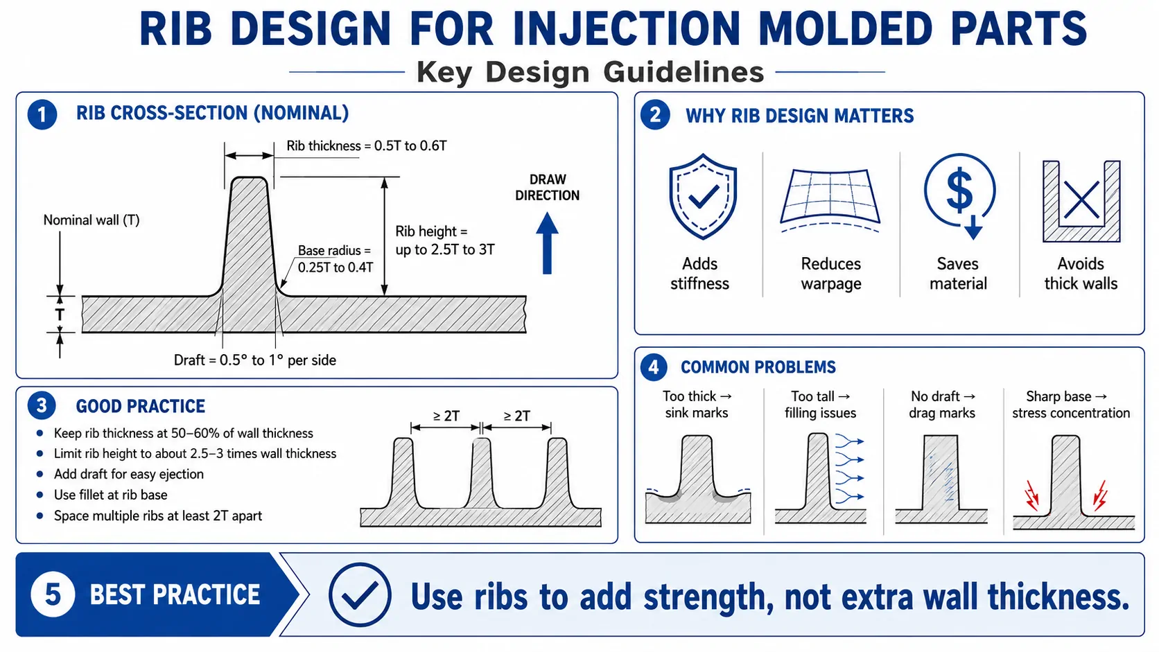
All values cross-referenced against verified DFM experience data. The base radius upper bound is corrected from a commonly cited 0.5× to the verified 0.4×. Height is shown as a range — so the practical target stays separated from the absolute max.
| Rib Feature | Recommended Range | Why It Matters | Common Failure If Ignored |
|---|---|---|---|
| Rib thickness (at base) | 40%–60% of wall T (40%–50% for high-shrink resins) | Controls sink marks | Visible sink on show surface |
| Rib height | ≤ 2.5× T (typical) / 3× T max | Keeps rib fillable and structurally stable | Short shots, buckling, gas traps |
| Draft per side | 0.5°–1.5° (+1° per 0.01 mm grain depth for textured surfaces) | Allows clean ejection | Drag marks, ejection damage |
| Base radius Corrected | 0.25–0.4× T | Balances stress relief with sink risk | Cracking (too small) or sink (too large) |
| Rib spacing | ≥ 2× T (center-to-center) | Prevents hot zones and steel weakness | Sink, voids, warpage |
| Strategy | Many thin ribs over one thick rib | Stiffness without sink mark | Heavy base, slow cycle, differential warpage |
| T = nominal wall thickness. Treat values as starting points; confirm with mold-flow simulation for your specific resin and geometry. | |||
What Defects Come From Bad Rib Design?
Bad rib design shows up in production, not in CAD. Knowing the failure modes lets buyers ask the right questions before the tool is cut.
Sink Marks
Caused by ribs above 60% of wall, or base radii above 0.4× T. Thick junction cools slowly. The opposite surface pulls inward.
Internal Voids
Vacuum bubbles form when a thick rib base freezes on the outside while the core is still shrinking. Hidden — but the part is weaker.
Short Shots
Incomplete ribs. Happens when height tops 2.5× T and the narrow section freezes before the melt reaches the tip.
Warpage
Uneven shrinkage from inconsistent spacing or lopsided layouts. One side dense, the other open. Part twists after ejection.
Weak Knit Lines
Two flow fronts meet inside a poorly filled rib and leave a weak seam. Tall ribs far from the gate are the usual culprits.
Ejection Damage
Scuffs, drag marks, stress whitening on ribs with too little draft. Worst on textured surfaces — grain depth demands more draft than designers expect.
How Does Material Choice Change the Rules?
Each resin shrinks and flows differently. So the 40%–60% rule is a baseline, not a law. Wall thickness variation across one part should also stay within ±25% of nominal. That avoids differential cooling and warpage. It’s a standard DFM requirement for the whole part — not just the ribs.
Semi-crystalline, high shrink. Target rib thickness 40%–50% of wall. Confirm with mold-flow before exceeding 2.5× rib height.
Amorphous, lower shrink. Rib thickness can approach 60% of wall. Keep base radius ≤ 0.4× T and full draft on cosmetic faces.
Stiffer, less flow-friendly. Adjust gate strategy so ribs fill cleanly. Size the gate about +10% vs. the unfilled grade to cut shear.
Push every value conservative. High-gloss needs 0.25°–0.5° draft. Gloss amplifies any sink. Texture can hide a minor depression.
Rib Design Checklist for Buyers
Run this checklist before approving the part for tooling. Every unchecked item is a risk to resolve before steel moves.
- Rib thickness is 40%–60% of the wall. Use 40%–50% for high-shrink or cosmetic parts.
- Rib height stays at or below 2.5× wall. Review mold-flow if it approaches 3×.
- Every rib has at least 0.5° draft per side. Textured ribs add 1° per 0.01 mm of grain depth.
- Base radii sit in the 0.25–0.4× wall range — not 0.5×.
- Rib spacing is at least 2× wall, center to center, and consistent across the part.
- The design favors several thin ribs over one thick rib wherever the load allows.
- Ribs align with the expected load direction for deflection control.
- Wall thickness variation across the part stays within ±25% of nominal.
- The supplier ran a DFM analysis and flagged any sink, fill, or warpage risk in writing.
How to Evaluate a Supplier’s DFM on Ribs
Judge a supplier on the design feedback they give you before quoting — not on price alone. A shop that runs real DFM catches rib problems while fixes are still cheap. A shop that skips it dumps that risk on you.
Ask for the DFM report in writing. A strong report names rib thickness ratios, calls out draft per face, predicts sink locations, and shows fill simulation results. It proposes specific fixes: split a thick rib, add draft, reduce height. Not “we’ll handle it.” Factory-direct mold makers who own the tooling turn this review faster. They also explain the trade-offs in plain language.
If your supplier can’t answer rib questions before quoting, that’s your answer. For buyers sourcing overseas, a documented DFM step also cuts communication risk. Rib decisions on paper now means no surprise sink — and no tool reworks — after T1.
Frequently Asked Questions
What is the ideal rib thickness for injection molding?
The verified range is 40%–60% of the nominal wall thickness at the rib base. Use 40%–50% for high-shrink semi-crystalline resins like polypropylene or nylon. Same lower end for cosmetic surfaces where any sink will show. For amorphous resins like ABS or PC you can approach 60%. Confirm against your material and mold-flow simulation.
Can ribs be the same thickness as the wall?
No. A rib at 100% of the wall almost always sinks the opposite surface. The thick junction cools slowly and pulls the show face inward. Hold the rib at 40%–60% of the wall. Add more ribs if you need extra stiffness.
How tall should ribs be in injection molding?
Aim for no more than 2.5× the nominal wall thickness as your routine target. Three times the wall is the absolute ceiling — and only after mold-flow confirms the rib will fill. Taller ribs risk short shots, trapped gas, and weak knit lines. Risk peaks in semi-crystalline resins and narrow ribs.
Do ribs always cause sink marks?
No. Ribs at 40%–60% of the wall with a 0.25–0.4× T base radius usually mold without visible sink. Texture on the show surface can hide minor depression. Oversized ribs — near or above 70% of the wall — almost always sink, regardless of process tuning.
How does rib design reduce part deflection?
Ribs raise the part’s moment of inertia — its resistance to bending. Bending stiffness scales with the cube of rib height. Even a modest rib cuts deflection sharply. Line ribs up with the load direction for the biggest effect.
What draft angle does a textured rib need?
Textured surfaces need draft on top of the base 0.5°–1.5°. The standard rule is 1° of extra draft per 0.01 mm of grain depth. So a 0.05 mm texture needs at least 5° of added draft on top of ejection draft. This is a physical demolding requirement. Confirm grain depth with your texture specialist before tooling.
Should I trust a supplier who does not review my ribs before quoting?
Be careful. Rib problems cost far less to fix in CAD than in cut steel. A supplier who flags rib risks early — thickness ratio, draft shortfall, predicted sink — protects your timeline and cost. One who skips this step may quote faster. You’ll pay it back in rework and delays at first shot.