7 Proven Boss Design Rules to Eliminate Cracks, Sink Marks, and Weak Assembly
Shop-floor boss design rules for screw strength, clean surfaces, and fewer tool changes.
Boss design causes more molded part trouble than many buyers expect. A boss looks like a simple round post. In the mold, it is a heat trap and a stress point. It also takes real load during assembly.
Get boss design wrong, and the damage shows fast. You see sink marks, split bosses, stripped screws, or loose housings. I have seen good-looking samples fail after one screw pass. The steel was fine. The boss geometry was not.
This guide is for buyers and engineers sourcing plastic parts. It explains boss design ratios, cracks, sink, fasteners, ribs, and supplier checks. Use it before tooling starts.
What Is a Boss in Injection Molding?
A boss is a raised molded post that accepts a screw, insert, pin, or mating part. Most bosses are round and hollow. The hole receives a screw, shaft, or threaded insert. The boss transfers fastener load into the part wall.
Bosses do more than hold screws. They align housing halves, support PCBs, set spacing, and carry clamp force. A weak boss can ruin an otherwise clean molded part.
Why Does Boss Design Decide Part Quality?
Boss design decides part quality because it controls stress, cooling, and assembly strength. Those three issues meet at the boss.
Extra plastic at the boss base cools slowly. That slow cooling causes shrinkage and sink. A sharp corner creates a stress riser. That stress riser becomes a crack after ejection or screw driving.
A thin or short boss also loses screw grip. The part may pass visual checks and still fail assembly. That cost usually appears after T1/T2, when changes already hurt.
Boss Design: Core Rules and Ratios
Good boss design starts with nominal wall thickness, usually called T. Every boss feature should scale from that wall.
The goal is not a heavy boss. The goal is a boss that cools evenly and holds load. Thick plastic causes sink. Sharp roots cause cracks. Poor draft causes sticking.
How Thick Should a Boss Wall Be?
The boss outer wall should be 0.4–0.6 × nominal wall thickness. This range limits sink while keeping screw support.
For a 2.5 mm nominal wall, target a boss wall near 1.0–1.5 mm. A full-thickness boss wall is risky. It creates a hot spot behind the cosmetic surface.
For most housing parts, start near the middle of the range. Then adjust for resin, screw size, and pull-out load.
How Wide Should the Boss Outer Diameter Be?
The boss outer diameter should give the screw enough plastic to bite. It must not create a thick plastic lump.
A common rule uses about 2 × inner hole diameter. Another check is 2–2.5 × screw shank diameter. These ratios balance pull-out strength and sink control.
Oversized bosses look stronger on CAD. In the mold, they often give you sink and longer cycle time.
How Tall Can a Boss Be?
A boss should stay at or below 2.5–3 × its outer diameter. Taller bosses need ribs or gussets.
Tall bosses are harder to fill. They can trap air near the tip. They also bend under side load. I would not approve a tall free-standing boss without support.
What Base Radius Prevents Cracks Without Causing Sink?
The base radius should be 0.25–0.5 × nominal wall thickness. Start near 0.25 × T for most parts.
A larger radius lowers stress. A smaller radius reduces mass. A sharp corner is the one choice I never accept. It invites boss cracking.
When strength is needed, add ribs before adding a heavy fillet. That move keeps the boss cooler.
| Boss Feature | Recommended Ratio / Value | Defect Prevented | Source |
|---|---|---|---|
| Boss outer wall thickness | 0.4–0.6 × nominal wall (T) | Sink marks | Verified DFM |
| Boss root floor thickness | 0.7–0.9 × nominal wall (T) | Root fracture, ejection damage | Verified DFM |
| Outer diameter | ~2 × inner hole diameter | Weak assembly / pull-out | Industry standard |
| Height (hole depth) | ≤ 2.5–3 × outer diameter | Short shots, deflection | Verified DFM |
| Base fillet radius | 0.25–0.5 × nominal wall (T) | Cracks and sink control | Verified DFM |
| Draft — outer surface | 0.5–1.5° per side | Sticking, drag marks | Verified DFM |
| Draft — inner bore | ~0.5° per side | Core pull damage, scuffing | Verified DFM |
| Use these values as starting points. Confirm them against your resin, screw, mold flow, and supplier DFM review. | |||
What Causes Cracks in Molded Bosses?
Boss cracks come from stress concentration and screw hoop stress. The screw pushes the boss wall outward.
If the pilot hole is too small, hoop stress rises fast. If the root corner is sharp, the crack starts there. Brittle or glass-filled resin gives you less room for error.
The main crack drivers are:
- Sharp internal corners. A zero-radius boss root creates a stress riser. Even a small fillet reduces peak stress.
- Overtightening or oversized screws. Excess hoop stress can split the boss wall.
- Weld lines at the boss. A knit line near a loaded boss often cracks first.
- Glass-filled or brittle resins. Stiff materials need better radii and correct pilot holes.
- Thread-forming screws in rigid resins. These screws push plastic outward. That can leave residual hoop stress in PC, PA66 GF, and similar resins.
What Causes Sink Marks Around Bosses?
Sink marks around bosses come from uneven cooling at the boss base. Thick plastic stays hot longer.
As the thick core cools, it shrinks and pulls the surface inward. That leaves a shallow dent on the show face. More packing can hide a mild sink. It cannot fix a boss that is too thick.
Reduce mass first. Keep boss wall thickness at 0.4–0.6 × T. Avoid solid blocks between the boss and wall. Use ribs and gaps instead. Core out thick areas where the design allows it.
Sink is mainly a geometry problem. Process changes can reduce a small sink. They cannot save an over-massed boss.
Why Do Bosses Fail During Assembly?
Bosses fail during assembly when they cannot hold fastener load. The failure usually traces back to geometry.
- Stripped threads — the pilot hole is too large for the screw.
- Boss splitting — the pilot hole is too small for the screw.
- Pull-out — the boss wall or thread engagement is too weak.
- Loosening over time — creep lowers clamp load during service.
For serviceable products, threaded inserts are often the better choice. Bare plastic threads wear quickly after repeated opening. A metal insert costs more, but it protects assembly life.
How Do Ribs and Gussets Reduce Boss Deflection?
Ribs and gussets reduce boss deflection by bracing the boss base. A tall boss bends like a post.
A gusset turns that post into a supported feature. It adds stiffness without making the boss wall too thick. That is the right trade.
Use these support rules:
- Add two to four gussets around tall bosses.
- Keep gusset thickness at 0.4–0.6 × nominal wall.
- Use a rib and gap when connecting a boss to a side wall.
- Use gussets as flow leaders for long or slender bosses.
Do not thicken the boss to solve bending. That often creates sink. Support the boss instead.
Self-Tapping Screws vs Threaded Inserts
The fastener choice drives the boss design. Choose the screw or insert before freezing the boss.
Self-tapping screws suit low-cost products assembled once. Threaded inserts suit serviceable products, stiff resins, and higher clamp loads. For rigid engineering resins, thread-cutting screws are often safer than thread-forming screws.
| Factor | Self-Tapping Screw | Threaded Insert |
|---|---|---|
| Unit cost | Lower | Higher, with insert and install step |
| Repeated assembly | Limited because plastic threads wear | Excellent because threads are metal |
| Pull-out strength | Moderate | High |
| Screw type recommendation | Thread-cutting for rigid PC or PA66 GF; thread-forming for ductile resins | N/A because the insert supplies the thread |
| Best for | High-volume parts assembled once | Serviceable products and rigid resins |
| Boss design impact | Pilot hole follows screw pitch diameter | Boss ID follows insert maker data |
| Crack risk | Higher when the hole is wrong | Lower because load spreads into the wall |
| For threaded inserts, follow the insert maker’s boss diameter and depth. Heat-set and ultrasonic inserts need different boss geometry. | ||
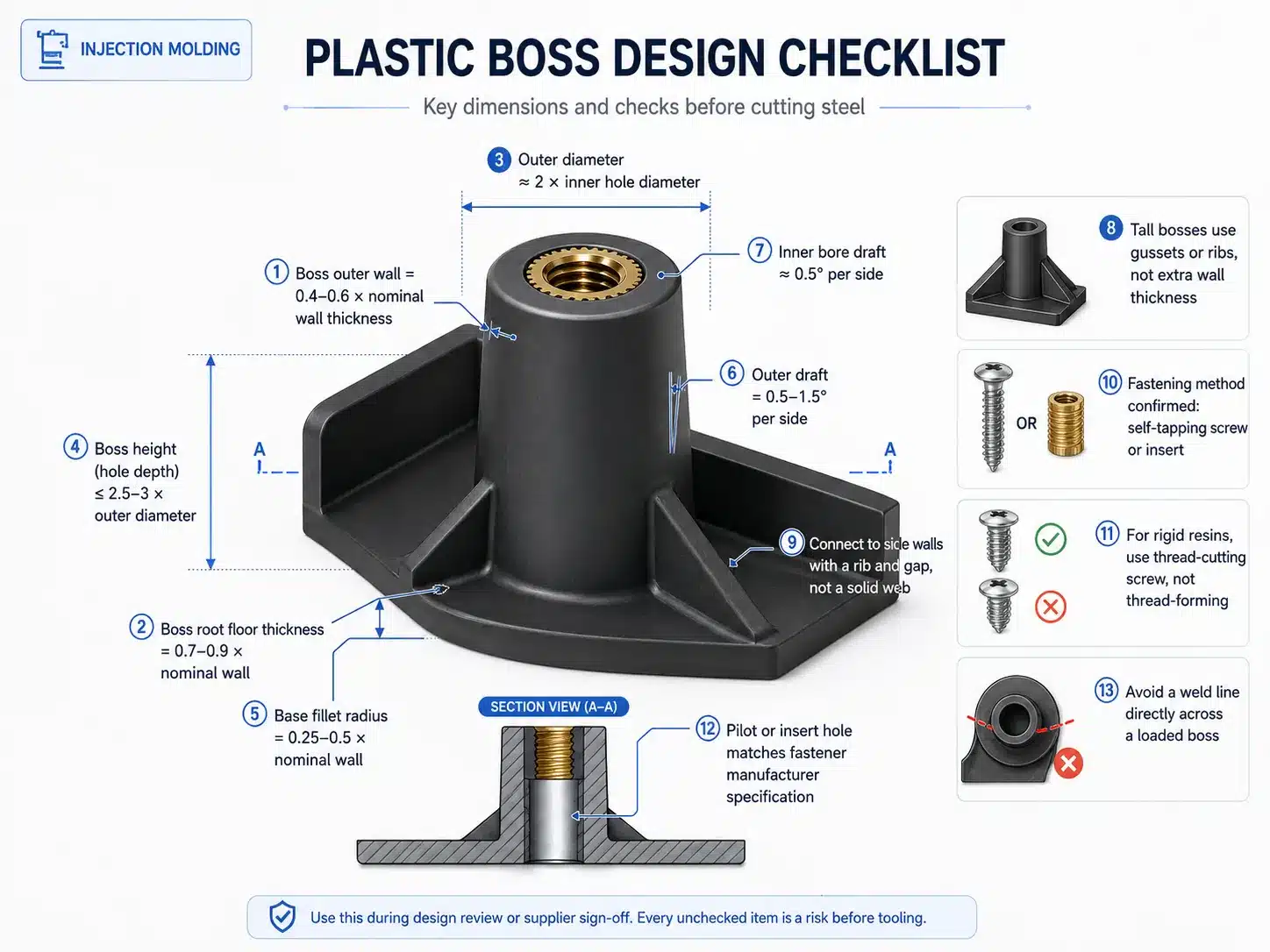
Boss Design Checklist and Decision Table
Use this checklist before tooling sign-off. Every unchecked item is a possible tool change.
- Boss outer wall is 0.4–0.6 × nominal wall thickness
- Boss root floor thickness is 0.7–0.9 × nominal wall
- Outer diameter is approximately 2 × inner hole diameter
- Boss height is no more than 2.5–3 × outer diameter
- Base fillet radius is 0.25–0.5 × nominal wall
- Outer surface draft is 0.5–1.5° per side
- Inner bore draft is approximately 0.5° per side
- Tall bosses have gussets or ribs, not extra wall thickness
- Boss connects to side walls with a rib and gap
- Fastening method is confirmed before final boss design
- Thread-cutting screws are specified for rigid resins where needed
- Pilot or insert hole matches the fastener maker’s data
- No expected weld line crosses a loaded boss
Quick Decision Table
| Defect or Symptom | Likely Root Cause | First Fix |
|---|---|---|
| Sink mark behind boss | Boss outer wall is too thick | Reduce wall to 0.4–0.6 × nominal wall |
| Crack at boss base | Sharp corner or brittle resin | Add fillet R ≥ 0.25 × T; verify screw fit |
| Stripped or loose screw | Hole size or wall mismatch | Resize pilot hole or use threaded insert |
| Boss flexes under side load | Unsupported tall boss | Add 2–4 gussets; reduce height if possible |
| Boss cracks after assembly in rigid resin | Thread-forming screw hoop stress | Use thread-cutting screw or heat-set insert |
| Boss damaged at ejection | Root floor too thin or bore lacks draft | Increase root floor to 0.7–0.9 × T; add bore draft |
How Should Buyers Evaluate a Molder’s Boss Design?
Buyers should judge the molder by design feedback, not price alone. A good supplier flags boss risks before quoting.
A weak supplier simply molds your CAD and waits for problems. That approach costs time during T1/T2. It also hides risk until assembly testing.
Ask these questions during sourcing:
- Does the DFM report check boss walls, radii, draft, and root floor thickness?
- Can the supplier run mold-flow checks for sink and weld lines?
- Will they review screw type against resin and assembly count?
- Will they show boss cross-sections during tooling review?
If your supplier cannot answer these, keep looking. Boss design is basic DFM work for a serious mold shop.
Frequently Asked Questions
What is the ideal boss wall thickness for injection molding?
How do I stop sink marks behind a screw boss?
Why does my plastic boss crack when I drive a screw?
Should I use a threaded insert or a self-tapping screw?
How tall can an injection molded boss be?
What draft angle does a boss need?
What is the difference between thread-forming and thread-cutting screws for plastic bosses?
Conclusion
Boss design is a set of linked proportions, not one simple rule. The wall, root, radius, draft, height, and fastener must work together.
Keep the boss outer wall at 0.4–0.6 × T. Keep the root floor at 0.7–0.9 × T. Add a 0.25–0.5 × T base fillet. Add draft inside and outside. Support tall bosses with ribs or gussets.
For buyers, the key is timing. Fix boss design during DFM, not after steel cutting. Ask for cross-sections, screw data, and mold-flow risk checks. A supplier who checks these details early protects your schedule and margin.