Importance of Wall Thickness in Injection-Molded Product Design
Injection-molded product design wall thickness is important to maintain the strength of part, surface finish, efficiency and cost control of the part. Irregular wall thickness may cause such problems as warping, sink marks, internal stress and uneven cooling. The industry standards dictate the specifications of the wall thickness design to be in line with the principles of smoothness, ease of material flow and ejection. Important points summarized as well as suggested values of common thermoplastics are presented below.
1. Simple Rules of Design of Wall Thickness
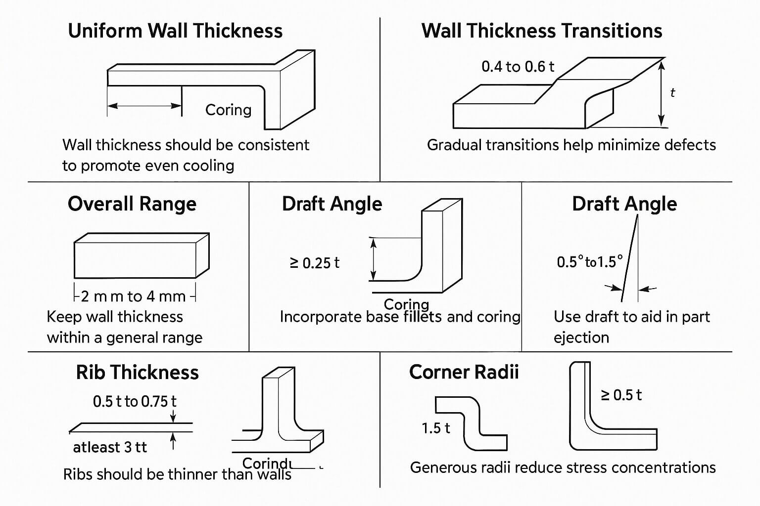
Constant Wall Thickness: It is important to maintain a constant wall thickness to allow melt flow and cooling to be uniform in order to minimize shrinkage related defects due to variations in thickness. Cores should be put in plastic parts to remove bulky areas and stereotypical uniformity as compared to metal parts.
Transition of Wall Thickness: There should not be a dramatic change in the ratio of adjacent wall thicknesses, less than 40 percent to 60 percent. The transitions in the wall thickness must be gradual in order to minimize stress concentrations, sink marks, voids, and warping.
Total Range: In general, wall thickness can be regulated between 2mm and 4mm (0.080in. to 0.160in.). Thickness of the wall should not be less than 5mm to avoid long cycle times and bad mechanical performance. Thin-wall injection molding can reach as low as 0.5mm however special molds and special materials are needed.
Gate Position: It is not recommended to position the gate close to locations where there are high changes in wall thicknesses as this will cause hesitation or race tracking of flow, resulting in an uneven fill.
Material Flow Consideration: In selecting the materials, ensure that you check the length of flow ratio. As an example, the ratio of PP flow length is 200-300 and PC is 30-100 hence sufficient filling in thin walled designs.
2. Suggested Thickness of Some Typical Materials in Walls
| Recommended Material | Wall Thickness (mm) | Remarks |
|---|---|---|
| ABS | 1.14 ~ 3.56 | This can be used on thin walls, it is also fluid, and can warp when glass fiber is included. |
| Acetal (POM) | 0.76-3.05 | High shrinkage (0.020-0.025 in./in.), accuracy parts. |
| Acrylic (PMMA) | 0.64 ~ 3.81 | It is utilized in thicker sections in order to prevent sink marks and in optical grades to make transparent sections. |
| Liquid Crystal Polymer (LCP) | 0.76 ~ 3.05 | Very strong, thin walled and free flowing. |
| Long-Fiber Reinforced Plastics | 1.91 ~ 25.4 | It can also be used to construct large structural parts and thick walls which makes it stiffer. |
| Nylon | 0.76 ~ 2.92 | Min 1.0mm in order to be structurally strong and easily absorbs moisture. |
| Polycarbonate (PC) | 1.02 ~ 3.81 | It can be used in optical components, thin wall parts will produce bubbles and sink marks. |
| Polyester (PET) | 0.64 ~ 3.18 | Thin walls can be obtained with low shrinkage. |
| Polyethylene (PE) | 0.76 ~ 5.08 | Good flow (250~275), can be thicker walls but easily warped. |
| Polyphenylene Sulfide (PPS) | 0.51 ~ 4.57 | High heat resistance and may have possible thin walled designs. |
| Polypropylene (PP) | 0.64 ~ 3.81 | Good flow (200-300), shrinkage rate 0.010-0.025 in./in., shrinkage is reduced by mineral fillers. |
| Polystyrene (PS) | 0.89 ~ 3.81 | High flow (200~250), brittle, thin walls can be used. |
| Polyurethane (PU) | 2.03 ~ 19.05 | Flexible, can be applied on thicker parts. |
Note: shrinkage values are wall thickness of 3.2mm (ASTM D955). Without fillers, shrinkage is more; with fillers, the shrinkage decreases at the expense of flow.
3. Design of Ejection and Draft Angle
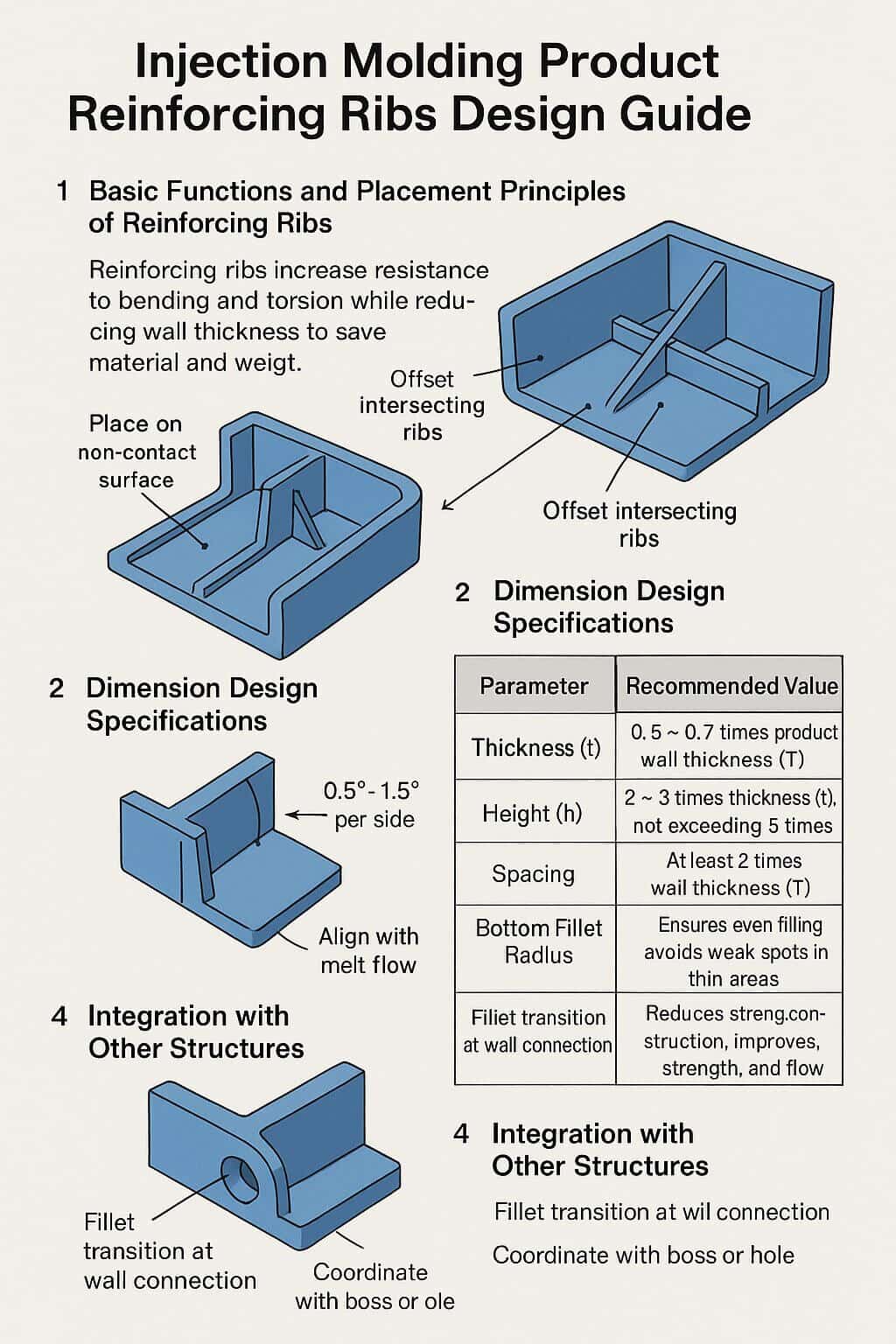
Draft Angle: Draft angle is suggested 0.5-1.5 degrees/side (1 degree per inch of cavity depth) to avoid ejection damage and internal stresses which cause warping.
Effect of the Wall Thickness on Draft Angle: The draft angle will need to be greater in thinner walls so that the ejection is smooth.
4. To Other Buildings Connection
Ribs: Rib thickness should be 50-75 percent of the nominal wall thickness and no more than 3 times the wall thickness and spacing should be 2.5 times the wall thickness. Balance ribs on both sides so that they do not warp.
Bosses: The wall thickness shall be the same as the standard wall, bottom fillet shall be 1/4 of the wall (minimum 0.38mm) and the bottom shall be cored to obtain uniformity.
Radiuses: Internal radius must be at least 0.5 the wall thickness and external radius must be wall thickness + internal (1.5 times), to minimize stress and mold costs. Interior corners must not be sharp.
Support Structures: To avert the lopsided cooling that is caused by the high walls, the 40%~60% rule must be observed by reinforcing the walls using the ribs or gussets.
5. Potential Issues and Suggestions on Optimization
Issues: Wavy wall thickness may cause warping, indentations, bubbles, inadequate filling and a prolonged cycle time. Greater wall thickness makes them more rigid (an increase of 10 percent in the thickness of walls can improve rigidity by 33 percent) but also more expensive and heavier.
Optimization: CAD Simulation (e.g. Moldflow) to study flow and stress. When choosing materials, put into consideration the shrinkage rates (e.g. semi-crystalline materials shrink more). Where it is thicker, coring should be used or ribs should be added to minimize material consumption.
Thin-Wall Design: It is applicable with high volume parts but it needs high injection pressure and tight molds.
