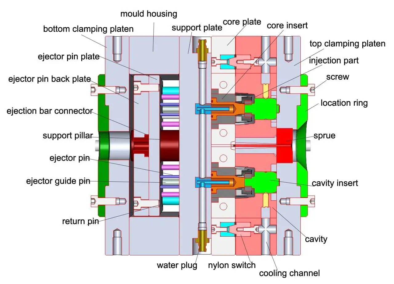
A plastic injection mold is a complex assembly of several components designed to create a desired plastic product. The main components of a typical injection mold structure are:
Mold Base
This is the main structure that holds all other mold components together. It is usually made of steel and provides support, alignment, and guidance for the other parts.
core and cavity
The core and cavity are crucial components of an injection mold, as they directly impact the quality and accuracy of the final plastic product. To ensure optimal performance, it’s essential to pay attention to the steel selection, design, and machining of these components.Steel Selection: The choice of steel for the core and cavity is critical, as it influences the mold’s durability, wear resistance, and ability to produce consistent parts. Commonly used steel types include:
- P20: A pre-hardened steel that is widely used for core and cavity components. It offers good machinability and polishability, as well as decent wear resistance.
- H13: A hot-work tool steel with excellent toughness, wear resistance, and high-temperature strength. It is suitable for high-volume production and is often used in molds for engineering plastics with abrasive fillers.
- S7: A shock-resistant tool steel with high toughness and wear resistance, suitable for molds with complex geometries and moving parts.
- Stainless steel (e.g., 420 and 440 series): Used in molds for corrosive materials or applications requiring high surface finish quality. These steels offer excellent corrosion resistance and polishability.
Design:
The design of the core and cavity must consider the following factors:
- Part Geometry: The core and cavity must accurately reproduce the desired part geometry while considering draft angles, undercuts, and other features that could affect the ejection and moldability of the part.
- Shrinkage: The design should account for the shrinkage of the plastic material during cooling. Shrinkage values vary depending on the plastic type and must be factored into the mold design to ensure proper dimensions of the final part.
- Parting line: The parting line is where the mold halves meet. The location of the parting line should minimize the visibility of the resulting seam on the final part, and take into account the ease of mold manufacturing and maintenance.
- Cooling and Venting: Proper cooling channel and vent placement in the core and cavity are essential to maintain consistent mold temperatures and prevent defects.
Machining:
Machining the core and cavity requires precision and accuracy to ensure high-quality parts. Key machining steps include:
Rough Machining: Using CNC milling or EDM (Electrical Discharge Machining) to remove the majority of the material, leaving enough material for final finishing and polishing.
Semi-Finishing: This step refines the core and cavity’s shape and removes any remaining tool marks from the rough machining process.
Finish Machining: High-precision machining operations are performed to achieve the final dimensions, tolerances, and surface finish required for the core and cavity. Techniques like CNC milling, grinding, and EDM are employed.
Polishing
The core and cavity surfaces are polished to achieve the desired surface finish. The level of polish depends on the requirements of the final part; a high-gloss finish may be necessary for optical components, while a lower polish may suffice for industrial parts.
Injection mold surface finish is the texture or roughness of the mold’s surface, which determines the appearance and quality of the final molded product. There are different types of surface finishes :
- Mirror finish: A mirror finish is the smoothest surface finish, which is achieved by polishing the mold with a fine abrasive material.
- High gloss finish: A high gloss finish is slightly less smooth than a mirror finish but still highly reflective, and it is achieved by polishing the mold with a polishing compound.
- Matte finish: A matte finish is a non-reflective, slightly rough surface that is often used for aesthetic purposes. It is achieved by using a sandblasting process or a chemical etching process to create a fine texture on the mold surface.
- Texture finish: Texture finishes are used to create a specific surface texture on the molded product. There are many different types of texture finishes, including leather grain, wood grain, and geometric patterns.
- Satin finish: A satin finish is a smooth, low gloss surface finish that is achieved by using a fine abrasive material to create a consistent, even texture on the mold surface.
- Mold-tech finish: Mold-tech finishes are a series of texture finishes that are commonly used in injection molding. These finishes range from light stippling to heavy texturing, and they are used to create specific surface textures on the molded product.
- EDM finish: EDM stands for electrical discharge machining, which is a process used to create precise, complex shapes on the mold surface. EDM finishes are typically very smooth and consistent.
| As machined | – | Finished to the machinist’s discretion | 3.20 (with visible machining marks) |
| Dull Textured finish | D-2 | Dry Blast #240 Oxide | 1.00 to 2.80 |
| Fine Matte finish | C-1 | 600 Grit Stone | 0.35 to 0.40 |
| Fine Semi-glossy finish | B-1 | 600 Grit Paper | 0.05 to 0.10 |
| High Glossy finish | A-2 | Grade #6, 3000 Grit Diamond Buff | 0.025 to 0.05 |
| Medium Matte finish | C-2 | 400 Grit Stone | 0.45 to 0.55 |
| Medium Semi-glossy finish | B-2 | 400 Grit Paper | 0.10 to 0.15 |
| Normal Glossy finish | A-3 | Grade #15, 1200 Grit Diamond Buff | 0.05 to 0.10 |
| Normal Matte finish | C-3 | 320 Grit Stone | 0.63 to 0.70 |
| Normal Semi-glossy finish | B-3 | 320 Grit Paper | 0.28 to 0.32 |
| Rough Textured finish | D-3 | Dry Blast #24 Oxide | 3.20 to 18.0 |
| Satin Textured finish | D-1 | Dry Blast Glass Bead #11 | 0.80 to 1.00 |
| Super High Glossy finish | A-1 | Grade #3, 6000 Grit Diamond Buff | 0.012 to 0.025 |
Sprue, Runner, and Gate:
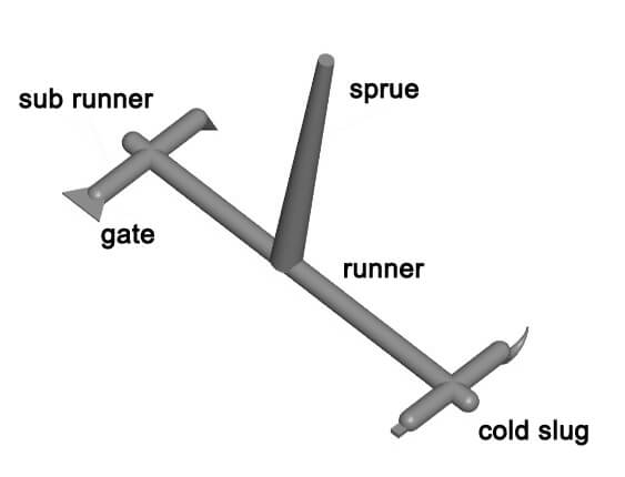
The gate and runner systems are essential components of an injection mold, as they facilitate the flow of molten plastic into the mold cavity. Here are some common gate styles and runner styles used in injection molding:
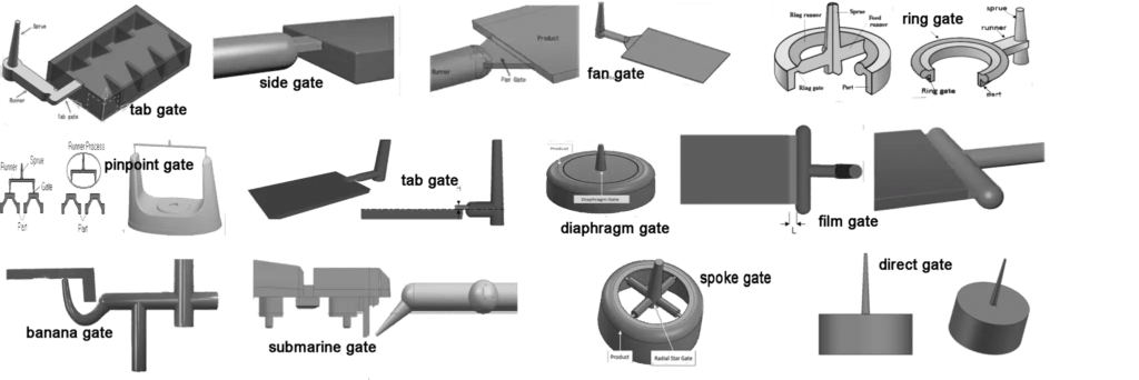
Gate Styles:
- Edge Gate: Located along the edge of the part, this gate style provides fast filling and is suitable for flat or thin parts. However, it may leave visible gate marks on the part surface.
- Submarine/Gate (Tunnel Gate): A gate that is located below the parting line and penetrates the mold cavity from the side or bottom. It automatically detaches from the part during ejection, minimizing the need for post-mold trimming.
- Hot Tip Gate: Used with hot runner systems, this gate connects directly to the nozzle tip and allows for precise control of the flow of plastic. It is suitable for parts that require minimal gate marks or vestiges.
- Fan Gate: A variation of the edge gate, the fan gate has a wider opening to distribute the plastic more evenly across a larger area. This gate type reduces stress concentrations and is ideal for thin-walled parts.
- Ring Gate: A circular gate that surrounds the core pin in a mold, ensuring uniform filling and minimizing flow marks. This gate type is commonly used for cylindrical or hollow parts.
- Diaphragm Gate: This gate is used for center-gated, thin-walled, and flat parts. It allows for even filling and minimizes weld lines and flow marks.
- Banana Gate (Curved Gate): A curved gate that extends from the runner into the cavity, often used in difficult-to-reach areas of a part. It detaches automatically during ejection.
- Pin-Point Gate: A small gate that leaves minimal gate vestige on the part. This type of gate is used for small or delicate parts that require minimal post-mold finishing.
- Tab Gate: Similar to an edge gate, but with an extended tab that can be more easily removed after molding. Tab gates are used when minimizing gate marks is essential, and they are often used for large or thick parts.
Runner Styles:
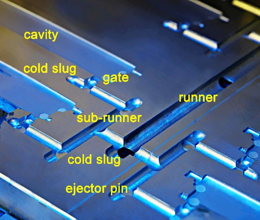
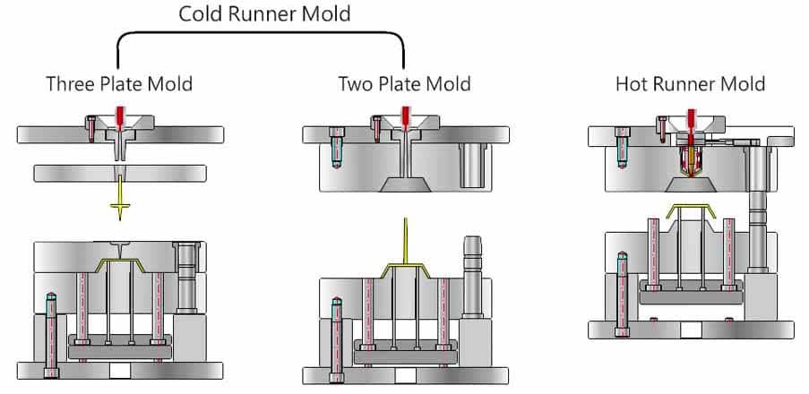
- Cold Runner: A system of channels in the mold that directs the molten plastic from the injection nozzle to the various cavities. The plastic in the runners solidifies and is ejected or removed along with the molded part, which can result in material waste.
- Unbalanced Runner: A simple runner layout that may result in uneven filling of the cavities and can lead to part inconsistencies.
- Balanced Runner: A runner layout designed to provide equal flow resistance and pressure to all cavities, ensuring consistent filling and part quality.
- Hot Runner: A system that maintains the molten plastic in a heated state within the runner channels. This eliminates the need for runner removal and reduces material waste. Hot runners often use heated nozzles or manifold systems to maintain the plastic’s temperature. Insulated Runner: A variation of the hot runner system where the runner channels are thermally insulated, maintaining the plastic in a semi-solid state. This system is used for certain materials or applications that require a specific temperature range.
The choice of gate and runner styles depends on factors such as part geometry, material, and production requirements. The right combination ensures a smooth, efficient, and consistent injection molding process.
Ejection System:
The ejection system is a critical component of an injection mold, as it ensures the safe and efficient removal of the finished plastic part from the mold cavity. A well-designed ejection system minimizes the risk of part damage and ensures consistent cycle times. The primary elements of an ejection system are:
Ejector Pins: These are the most common ejection mechanism used in injection molding. Ejector pins are thin, cylindrical rods that extend through the mold base and push against the solidified plastic part to eject it from the mold cavity. They are typically made of hardened steel to withstand the force and wear associated with repeated ejection cycles. The placement, size, and number of ejector pins should be carefully considered to provide adequate support and minimize part deformation or damage.
Ejector Sleeves: Ejector sleeves are hollow cylindrical components used when a standard ejector pin cannot be employed, often due to the part geometry or the presence of a core pin. They work similarly to ejector pins but surround the core pin, providing support and applying even force during ejection. Ejector sleeves are typically used in conjunction with ejector pins to ensure the smooth release of the part from the mold.
Stripper Plates: Stripper plates are flat plates that separate from the mold core and apply uniform force across the entire part surface, pushing the part out of the mold cavity. They are particularly useful for parts with large, flat surfaces, thin walls, or complex geometries where ejector pins may cause damage or deformation. Stripper plates can be actuated mechanically or hydraulically, depending on the mold design and requirements.
Ejector Blades: These thin, flat steel components are used in situations where ejector pins may damage or deform the part, particularly in areas with thin walls or small ribs. Ejector blades provide more surface area to distribute the ejection force, minimizing the risk of damage to the part.
Air Ejection: In some cases, compressed air can be used to help eject the part from the mold cavity. Small air channels are built into the mold, and once the part is solidified, compressed air is forced through these channels, helping to release the part from the mold. This method is typically used in conjunction with other ejection mechanisms, providing additional assistance during the ejection process.
The design and selection of the appropriate ejection mechanism(s) depend on factors such as part geometry, material properties, and production requirements. A well-designed ejection system ensures the smooth, efficient, and consistent removal of plastic parts from the mold, minimizing the risk of damage and maintaining optimal cycle times.
Cooling System:
The cooling system is a vital part of the injection mold design, as it ensures proper temperature control, which directly impacts part quality, cycle times, and overall efficiency. When designing a cooling system, several factors need to be considered, including the diameter of cooling channels, distance to the steel face, and minimizing turbulence. Here’s a closer look at these factors:
Diameter of cooling channels: The diameter of cooling channels influences the flow rate and heat transfer efficiency within the mold. There is no one-size-fits-all value for channel diameter, as it depends on factors like part size, mold size, and material being used. However, a common rule of thumb is to use cooling channels with a diameter of 3/16 inch (4.76 mm) to 1/2 inch (12.7 mm). Larger channels provide better flow and heat transfer but require more space in the mold, which may not be feasible for smaller or more intricate molds.
Distance to the steel face: The distance between the cooling channels and the mold surface (steel face) affects the efficiency of heat transfer from the mold to the cooling medium (usually water). As a general guideline, the distance should be approximately 1 to 1.5 times the channel diameter. This ensures effective heat transfer without compromising the mold’s structural integrity. However, the specific distance should be determined based on part geometry, material properties, and cooling requirements.
Minimizing turbulence: Turbulence in the cooling channels can impede the flow of the cooling medium and reduce heat transfer efficiency. To minimize turbulence, the cooling channel layout should promote laminar flow (smooth, parallel flow) rather than turbulent flow (disordered, swirling flow). Some design practices to minimize turbulence include:
- Using straight, parallel channels whenever possible
- Ensuring smooth transitions between sections with different channel diameters
- Avoiding sharp bends or corners in the cooling channel layout
- Using flow restrictors or flow regulators to maintain consistent flow rates
the sizes and parameters for the cooling system of an injection mold:
- Cooling system sizes:
- Cooling water pipe diameter: generally Φ6-Φ20, depending on the specific situation.
- Cooling hole diameter: usually Φ4-Φ8, but can be designed larger as needed.
- Cooling hole depth: generally 70%-80% of the mold thickness.
- Number of cooling water outlets: determined by specific mold size, shape, etc.
- Cooling system parameters:
- Cooling water flow rate: generally around 5-10 liters per minute.
- Cooling water pressure: generally 0.2-0.4 MPa.
- Cooling water temperature: generally 20-25℃.
- Cooling time: determined by specific mold size, shape, etc.
Mold Width Vs Diameter Of Cooling Channel
| Mold width | Diameter of cooling channel |
| width < 200mm | 5-6 mm (or 3/16″-1/4″) |
| 200mm<width<400mm | 6-8mm (or 1/4″ – 5/16″) |
| 400mm<width<500mm | 8-10mm (or 5/16″-3/8″) |
| 500mm<width | 10-13mm (or 3/8″-1/2″) |
Venting System:
The venting system plays a critical role in the injection molding process, as it allows trapped air and gases to escape from the mold cavity during injection. Proper venting helps prevent defects, such as short shots, burn marks, and other quality issues in the final product.

When designing the venting system, it’s essential to consider the depth, width, and distance of vent slots to ensure optimal performance:
- Depth of vent slots: Vent slots should be shallow to allow the escape of air and gases without letting molten plastic flow into them. The depth of the vent slots typically ranges from 0.0005 inches (0.013 mm) to 0.002 inches (0.051 mm) but may vary depending on the material used and the specific molding conditions. The vent depth should be selected to strike a balance between effective venting and preventing plastic from flashing (leaking into the vents).
- Width of vent slots: The width of vent slots can vary depending on the part size and geometry, but a common range is between 0.060 inches (1.5 mm) to 0.250 inches (6.35 mm). Wider vent slots allow for better airflow and can improve venting efficiency. However, the vent slot width should not compromise the mold’s structural integrity or result in excessive material removal from the mold.
- Distance of vent slots: Vent slots should be strategically placed throughout the mold cavity to ensure proper venting of air and gases. They are typically placed near the last areas to fill, where the plastic flow fronts meet (to minimize weld lines), and at any other locations where trapped air or gases may cause defects. The distance between vent slots depends on the part geometry, mold design, and specific molding conditions. Regularly spaced vents around the mold cavity can help ensure even venting and reduce the risk of defects.
In addition to vent slots, other venting methods can be employed, such as:
- Parting line vents: Small gaps or channels on the parting line of the mold, which allow trapped air and gases to escape.
- Ejector pin vents: Clearances around ejector pins can be utilized for venting, as they provide a path for air and gases to escape.
- Porous mold materials: Materials like sintered metals or porous steel can be used in specific mold sections to allow air and gases to escape through the mold material itself.
Proper venting system design is essential to ensure the high quality of the final plastic product. By carefully considering the depth, width, and distance of vent slots, and employing other venting methods when necessary, you can minimize defects, reduce cycle times, and improve overall molding efficiency.
other system
- Alignment System: This includes guide pins, bushings, and other components that ensure precise alignment between the core and cavity. Proper alignment is crucial to prevent damage to the mold and ensure accurate part formation.
- Mold Clamping System: This system holds the mold halves together during the injection process. It includes clamping plates, tie bars, and the clamping unit of the injection molding machine.
- Mold Release System: This includes mold release agents or coatings that are applied to the mold surface to facilitate part ejection and prevent the part from sticking to the mold.
safety
Operating an injection molding machine and handling injection molds involve various safety risks. To ensure the safety of workers and to prevent accidents, it is essential to follow safety guidelines and best practices when working with injection molding equipment. Here are some safety tips for operating injection molding machines and handling injection molds:
- Training: Ensure that all operators and personnel working with injection molding machines and molds have proper training and are aware of safety procedures and guidelines. Regular training sessions and updates can help maintain a safe working environment.
- Personal Protective Equipment (PPE): Workers should wear appropriate PPE, such as safety goggles, gloves, ear protection, and closed-toe shoes, to protect themselves from potential hazards, such as hot surfaces, molten plastic, and high noise levels.
- Machine guarding: Injection molding machines should have safety guards, such as interlocks and gates, to prevent access to moving parts and hot surfaces during operation. These guards should be well-maintained and in proper working order.
- Lockout/tagout procedures: Follow lockout/tagout procedures when servicing or maintaining injection molding machines to ensure that the equipment is de-energized and cannot be accidentally started.
- Mold handling: Use proper lifting equipment and techniques when handling heavy molds. Ensure that the mold is securely clamped and aligned before starting the injection process. Inspect molds regularly for signs of wear, damage, or defects that could pose safety risks.
- Purging procedures: Follow proper purging procedures when changing materials or cleaning the injection unit. Use appropriate purging compounds and ensure that the machine is at the correct temperature and pressure settings.
- Ventilation: Ensure adequate ventilation in the workspace to prevent the buildup of potentially harmful fumes and vapors produced during the injection molding process.
- Emergency stops: Make sure that emergency stop buttons are easily accessible and functional. Workers should be trained on when and how to use emergency stops in case of an issue.
- Regular maintenance: Perform regular maintenance on injection molding machines and molds to ensure they are in good working condition. This includes checking for wear, leaks, and other potential issues that could lead to accidents or malfunctions.
- Housekeeping: Keep the workspace clean and free of clutter to minimize tripping hazards and improve overall safety. Dispose of waste materials, such as sprues, runners, and purge material, in designated containers.
By following these safety guidelines and best practices, you can minimize the risk of accidents and create a safer working environment for operators and other personnel involved in the injection molding process.